Einleitung
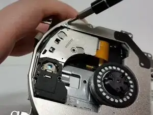
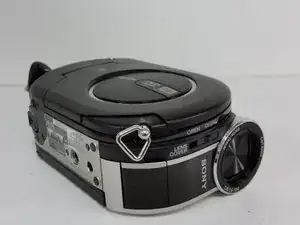
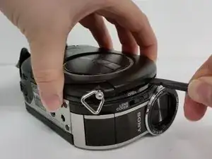
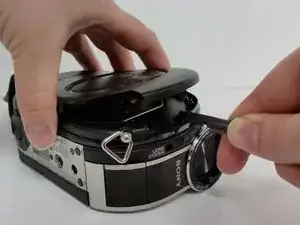
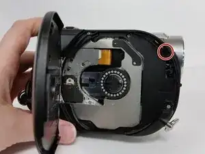
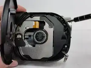
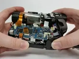
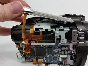
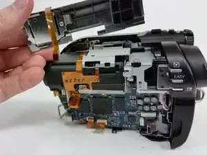
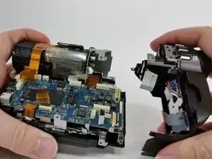
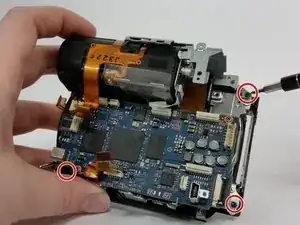
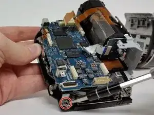
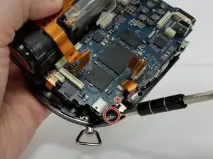
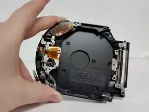
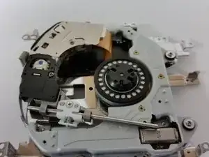
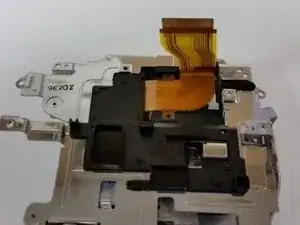
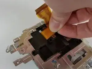
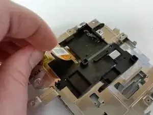
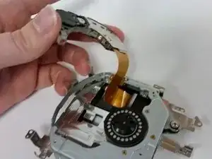
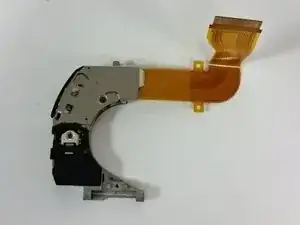
This guide will provide a basic overview of how to replace the laser assembly in a Sony Handycam DCR-DVD650. If your device seems to be functioning normally but it will not read or write, the issue may be with the laser. Please exercise caution with the lens as it can be easily damaged.
Before trying this repair, we would recommend gently cleaning the lens with a cotton swab and 90+ proof rubbing alcohol, making sure the area is as dust free as possible to avoid scratching the lens. Let it dry completely and test to see if this corrects the issue, the laser may just be out of focus.
There are many small parts that may fall out when executing the steps in this guide, be sure to take your time disassembling and reassembling your device and try to work on a clean, flat surface.
Werkzeuge
-
-
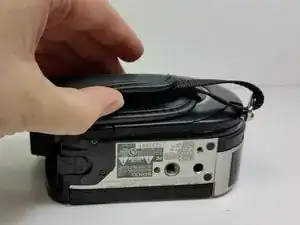
The hand strap can become a hindrance at times. It's best to begin by unlatching it.
-
On the padded section of the hand strap, pry up the Velcro and peel out the thin strap sandwiched between them.
-
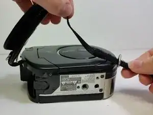
Push the thin strap through the metal loop at the front of the device.
-
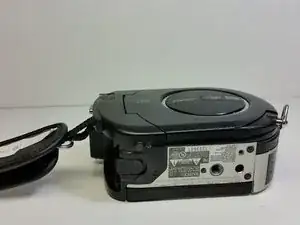
The strap will still be connected at one end to the device, but will be able to be moved out of the way to provide a more stable working surface.
-
-
-
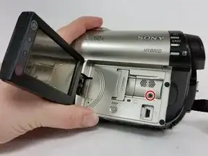
Flip open the LCD screen and find the screw located above the micro USB port.
-
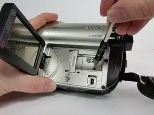
Remove the screw (4mm, Phillips #00)
-
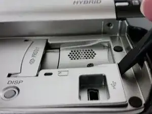
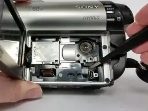
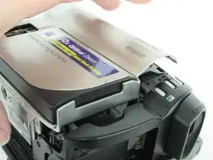
Using a spudger, or another small plastic prying tool, pop up the silver panel.
-
-
-
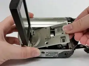
Once the silver cover is pried up, slip the piece out to the right.
-
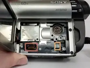
There are two cables attached to the board beneath that need to be disconnected.
-
Disconnect both of the no-fuss ribbon cables.
-
Use your fingernails or a pair of tweezers to pull on the tabs on either side of the ribbon cable to remove.
-
Remove the other cable by pulling up on the cable itself.
-
-
-
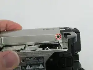
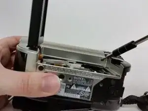
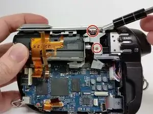
Locate the screw (Phillips #00) found in the top right corner of the housing.
-
Remove the screw.
-
-
-
Close the LCD screen and turn the device over.
-
Insert your spudger or other plastic pry tool into the small gap between the device housing and the door.
-
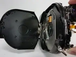
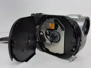
Pry open the door with the spudger, using your other hand to tug the door as you work it open.
-
-
-
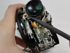
Once the disc door is open, locate the screw (Phillips #00) on the inside, top right corner, closest to the camcorder lens.
-
Remove the screw.
-
-
-
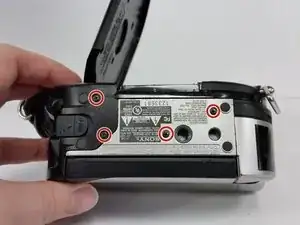
Turn to view the bottom of the device and locate the four screws on the bottom (4mm, Phillips #00).
-
Remove all four screws.
-
-
-
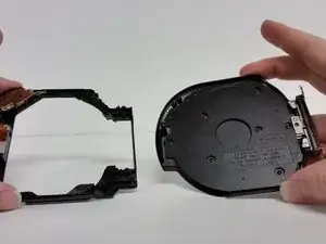
With the screws removed, the black and silver housing pieces should be able to shift apart from one another.
-
Gently work the black and silver housing pieces away from one another.
-
-
-
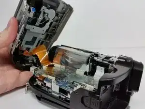
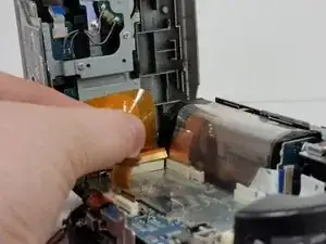
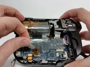
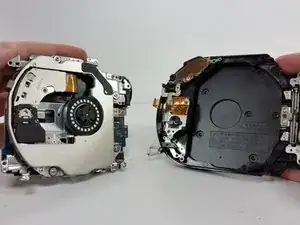
Once the device is open, carefully remove the no-fuss ribbon cable from the motherboard and set aside the silver portion of the device.
-
There may be a piece of plastic adhesive shielding the motherboard. Remove gently, being careful not to pull on the ribbon cables beneath it, and set aside.
-
-
-
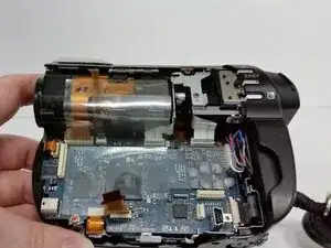
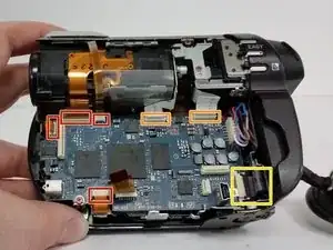
Locate all of the cables attached to the motherboard.
-
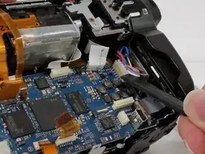
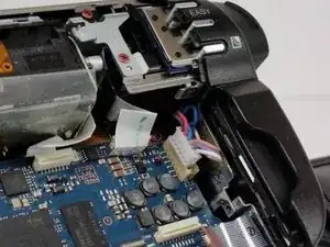
Carefully disconnect all cables.
-
There are four orange no-fuss ribbon connectors. To disconnect these cables pull up on the tabs protruding from both sides of the cable rather than pulling on the cable itself.
-
There are two white no-fuss ribbon cable connectors. To disconnect these cables, pull them straight out of the connector.
-
In the lower corner on the far right, disconnect the Zero-Insertion Force (ZIF) connector by flipping up the small black bar before removing the cable.
-
-
-
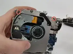
Now that all of the cables are disconnected, remove the two bronze screws (2mm, Phillips #00) on the lens housing.
-
Next we'll need to remove some screws from inside the disc housing.
-
If the disc door has closed at some point, turn the camcorder lens toward you and locate a small cylindrical lever to the left of the lens.
-
Pushing down on this lever will manually release the door.
-
-
-
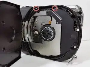
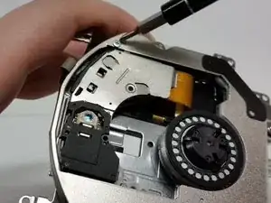
Remove the top two upper screws (4mm, Phillips #00) on the interior of the DVD housing.
-
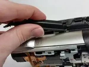
Pry up the black strip of housing between the open slider and the remaining silver housing above the lens.
-
A bit of a gentle tug and wiggle of the piece towards the lens side of the device, should allow you to completely remove the piece.
-
-
-
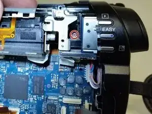
Remove the bronze screw (2 mm, Phillips #00) attaching the rear housing to the frame.
-
Once the screw is removed, the rear housing can be gently pulled away.
-
-
-
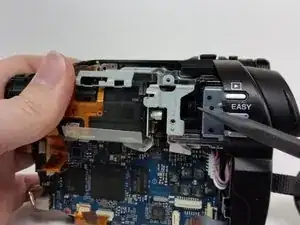
With the screw removed, lift up the silver panel above the lens assembly and slide it out towards the lens.
-
The rear housing should be able to be tugged apart with a small snap.
-
Set aside the rear housing.
-
-
-
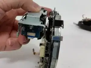
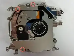
Remove the three black screws (5 mm, Phillips #00) connecting the frame to the disc housing.
-
-
-
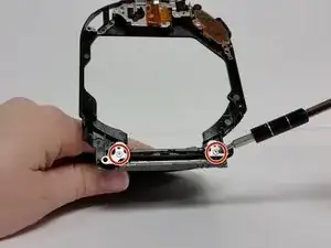
Remove the two outer screws (4mm, Phillips #00) from the hinge.
-
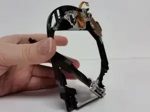
Opening the door to a full 90 degrees, should allow the door to be tugged up and out from the disc door frame.
-
-
-
After the disc door is separated from the frame, set aside.
-
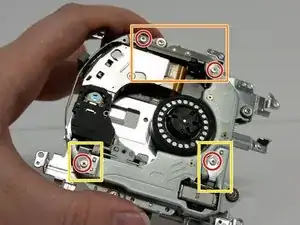
Remove the two bronze screws (2mm, Phillips #00) at the top of the metal frame.
-
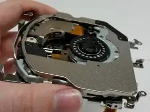
Separate the disc reading frame from the optical housing frame and set the optical housing aside.
-
-
-
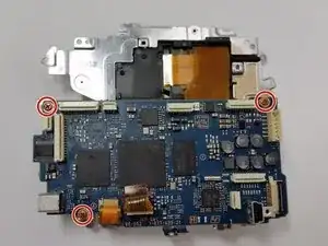
Locate and remove the three bronze screws (2mm, Phillips #00) attached to the motherboard.
-
Shift the board up carefully away from the rest of the assembly.
-
-
-
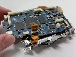
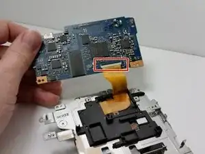
Locate where the ribbon cable is attached on the back of the motherboard.
-
Use a spudger or small pry tool to lift the black flap on the zero insertion force (ZIF) connector which secures the ribbon.
-
Gently remove ribbon and replace motherboard.
-
-
-
Locate and remove the three small, silver screws (2mm, Phillips #00) attaching the cover plate.
-
Remove the cover plate by tugging up slightly and to the right.
-
-
-
Remove the screws (2mm, Phillips #00) that hold the lens assembly in place.
-
Pull up the cover plates that have just been unscrewed.
-
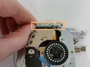
The top bar hold in place a small, black sliding rail. This will fall out once the cover plate is removed. Set aside with the cover plate and screws and make sure to mark the parts.
-
The bottom outer screws, hold a silver sliding rail in place, which will come undone once the plates and screws are removed. Again, set aside the cover plates and screws, making sure to mark the parts.
-
-
-
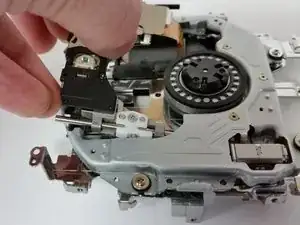
With the slider's cover plates removed, shift the laser assembly up slightly and out to the left.
-
-
-
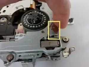
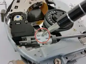
Unscrew the screw (2mm, Phillips #00) from the white, plastic piece on the silver sliding rod and set aside.
-
Slide out the silver sliding rod.
-
The optical assembly is almost ready to be removed.
-
-
-
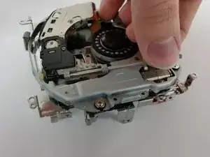
Turn the device over again.
-
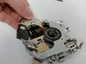
Unthread the ribbon cable.
-
The lens assembly is separated from the device.
-
To reassemble your device, follow these instructions in reverse order.
Ein Kommentar
That work on my handycam dvd810 dvd708.
