Einleitung

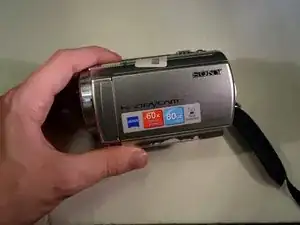
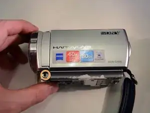
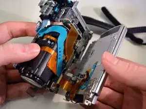
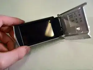
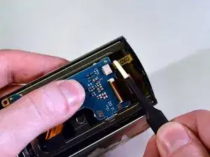
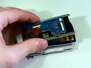
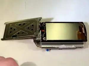
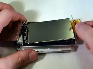
Can't view your pictures anymore after dropping your camera, and breaking the screen ? This guide will help you replace your LCD screen, so you can enjoy your camera once again.

  1. krxBJTBqGmakCF2O
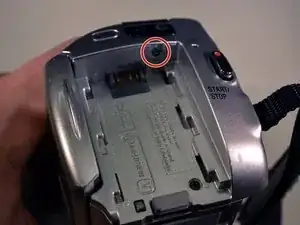
    • Wash and dry your hands, then put on a properly grounded anti-static wrist strap, before handling internal electronic components. To ground the wrist strap, attach it to the metal chassis of a plugged-in three prong power supply, of a computer for example.

    • Unfasten the hand strap.

    • Remove the battery.

  2. md3GSCHAGXAXtmxf
    md3GSCHAGXAXtmxf
    P241MHTyOjjJTYHx
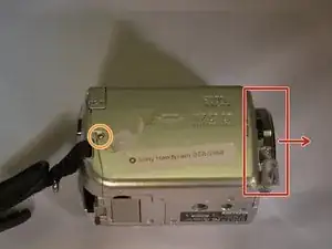
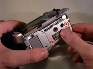
    • Place device on left side with front lens facing right.

    • Using a JIS size #00 precision Phillips screwdriver, unscrew the left middle 3mm Phillips screw.

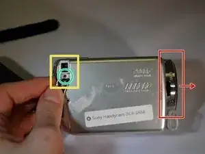
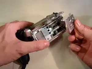
    • Open the "DC IN" plastic tab (Second 3mm Phillips screw is revealed).

    • Unscrew the second 3mm Phillips screw.

  3. nauxsC5ATRsZjIBK
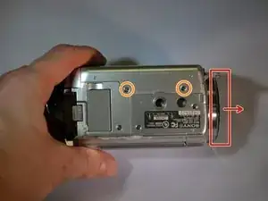
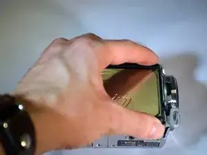
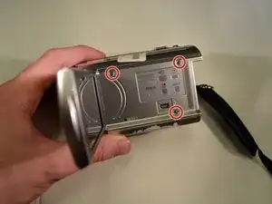
    • Turn device over onto its top with the front lens facing right.

    • Unscrew the top left and top right 3mm Philips screws.

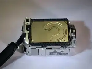
    • The right side case panel is now unfastened (the case panel facing up in the photo).

  4. 5OBv1Q6qPRLfAUej
    5OBv1Q6qPRLfAUej
    Mvtm6vEyuHgyOIrr
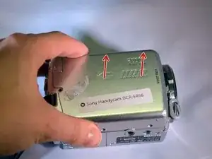
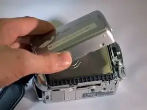
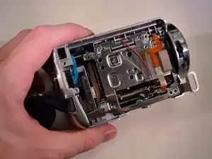
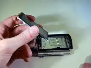
    • Remove the right side case panel by pulling up.

    • The Hard Drive (HDD) is now revealed.

    I need a hard drive

    Rajib Sahoo -

  5. m1UUaIFRY3JULUIe
    m1UUaIFRY3JULUIe
    fxg3ZPfm1KTVOEwL
    jg4RkuSthod1iUcZ
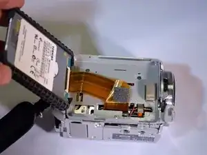
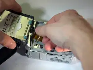
    • Using your fingers, lift the HDD from its right end, pivoting on its left end.

    • The HDD ribbon wire is now exposed.

  6. QnCtIMk1sgQAHfHU
    QnCtIMk1sgQAHfHU
    AsqAraXGFIiI5b2X
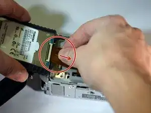
    • While securely holding the HDD in your left hand, use the soft pad of your right hand fingers to gently pull the ribbon wire out of its socket, toward your right.

    • The HDD is now free from the device.

    • Replace HDD.

  7. eVbR4JB6fkJ2OC3N
    • Follow steps steps 1-6 on HDD removal.

    • Once completed set aside HDD.

  8. 64VxSYALiFJaGvCP
    64VxSYALiFJaGvCP
    NpZ6kyPRnOLHv4JR
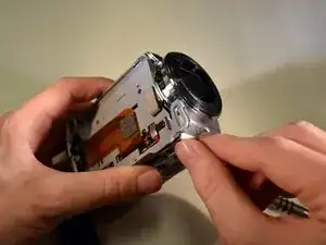
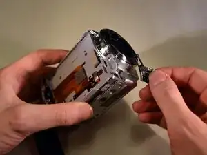
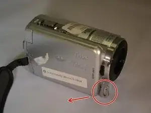
    • Remove the A/V tab

  9. 3qaGNFUGrUA45Gvo
    3qaGNFUGrUA45Gvo
    L6OIUM6I5TDPTlE5
    • Remove the right and middle bottom 3mm Philips screws from the bottom of the device.

    • Then remove panel.

  10. JXTZUGFhOWOedbDh
    JXTZUGFhOWOedbDh
    VQsOlBcWO3RiftHS
    • On the left side of the device, remove all visible 3mm Philips screws.

  11. RAsqBgVJICDsDgUF
    RAsqBgVJICDsDgUF
    LfKSAZHsQiJMACHR
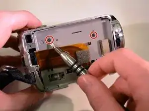
    • On the right side of the device, remove the two black 3mm Philips screws.

    • The grey tray is now loose.

    • Remove the grey tray by lifting out and away.

  12. sW3ZAcUXlwZEiMlE
    sW3ZAcUXlwZEiMlE
    yXSeOHmHWXGYSJxb
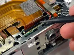
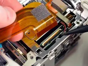
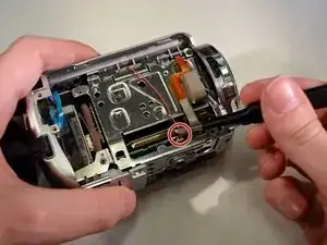
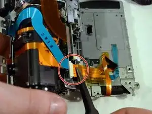
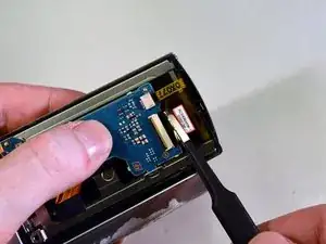
    • Using the black spudger, carefully open the little black clasp on the large ribbon wire port.

    • These clasps are known to be fragile.

    • On reassembly, this wire and clasp can be troublesome to reinstall.

  13. sXurnXkUmoFCfLpL
    sXurnXkUmoFCfLpL
    oPHLeGqdpSXAvaTf
    GSomyBPlYYodNReo
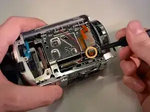
    • Using the blunt tweezers, unplug the red and black wire by gently pulling out and away.

    • Unplug the small ribbon wire.

  14. vDJXLXx6aWH25srx
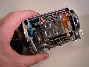
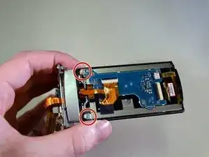
    • On the right side of the device, remove the top three right 3mm Philips screws.

  15. tJVohH3SZadTvya1
    • On the back of the device, remove the top 3mm Philips screw.

    • The top of the device is now free.

  16. 2LGOpcd1umUFNg1n
    2LGOpcd1umUFNg1n
    OnsHUH1MH3PUtPHO
    • Remove top of device by lifting up and away.

  17. SOJphrLGPWEybsh1
    SOJphrLGPWEybsh1
    uuDOO1YgKRyHHqjq
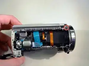
    • On the top of the device, remove the top right 3mm Philips screw.

    • On the left side of the device, remove the bottom left 3mm Philips screw.

  18. Nrjs1cjpdJXARw2U
    Nrjs1cjpdJXARw2U
    lPBffpREtRTiCRfl
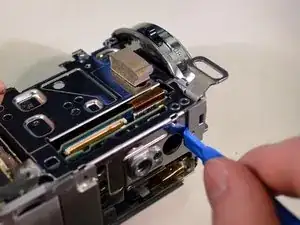
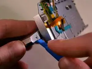
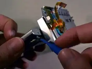
    • Use the blue plastic opening tool to pop the shutter assembly off the device.

  19. MyqC1fZmoBAGTLuE
    • On the left side of the device, remove the middle left 3mm Philips screw.

  20. HVL6RnuVRmqty5dV
    HVL6RnuVRmqty5dV
    UObRn1ChaEjZQTCc
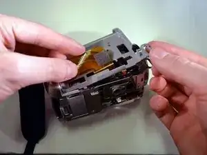
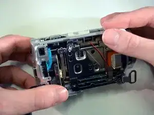
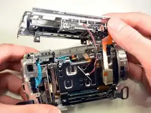
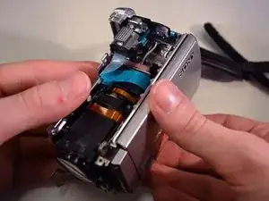
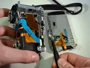
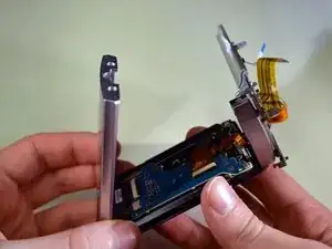
    • Carefully pivot the loose left side of the device until the ribbon wires are fully exposed.

  21. jfC4AS1Imw2lYgJ6
    jfC4AS1Imw2lYgJ6
    JXNDXoE5WHMXIEeb
    uNoiVqZVX2GM6xXe
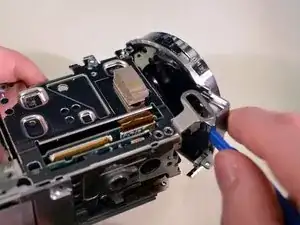
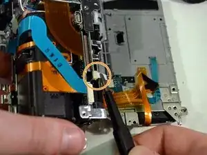
    • Using the blunt tweezers, unplug the small orange ribbon wire.

    • Unplug the small white ribbon wire.

    • The left side of the device is now free.

  22. PerR4xQfNu3jjW2q
    PerR4xQfNu3jjW2q
    3NeASB5RZJTfLQGH
    WBJj5hdDT5mpxkbj
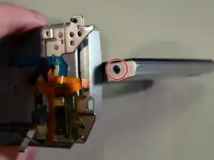
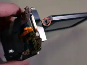
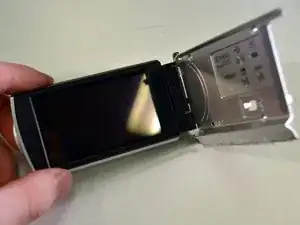
    • Open the screen and rotate it 90 degrees until the two black screws are exposed.

    • Remove the two black 3mm Philips screws.

  23. oR3KZbLIZlFbQFd4
    oR3KZbLIZlFbQFd4
    MjXXrxW2Bba1KRAi
    wD3MbySsAd4utcnO
    • Use a plastic opening tool to pop open the casing around the screen.

    • The casing may require some finesse to pop open.

  24. 1I4XPp2QeMp3CFEU
    • Remove two silver 3mm Philips screws on left side.

  25. HhUbATT2SZRSKe3R
    HhUbATT2SZRSKe3R
    LgPeGcJarRc6EUAH
    • Use the blunt tweezers to unplug both right side ribbon wires.

  26. gbHwmCJkDZUAyHVO
    gbHwmCJkDZUAyHVO
    Yy6PPIRHqwvAhg1K
    • Lift the framework up and pivot to the left.

    • The screen is now expose.

  27. BaZdalt5ia1IjnUr
    BaZdalt5ia1IjnUr
    U4TJ1aYE3VZ6pQTj
    • Lift out the screen by grabbing the ribbon wire and lifting up and out.

Abschluss

To reassemble your device, follow these instructions in reverse order in addition to the HDD Replacement guide.
alejandro zuniga

Mitglied seit: 07/01/16

736 Reputation

0 Kommentare