Einleitung
In this guide, you will go through the process of removing the camera's LCD screen. Please note that this involves thorough disassembly of nearly the entire camera, and should only be done if you absolutely need direct access to the screen.
-
-
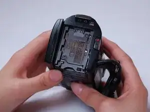
At this point, you should be able to remove the battery by simply lifting it from the camera.
-
-
-
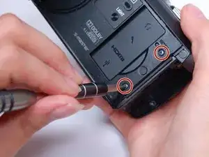
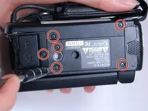
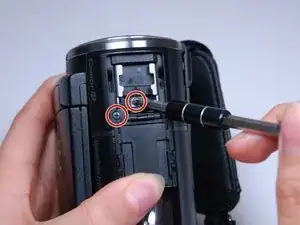
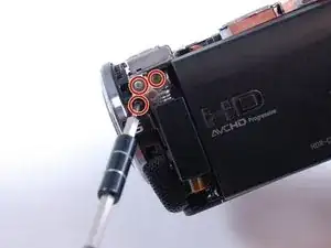
Use the Phillips #00 head to remove the following 5.5mm screws on the empty battery socket.
-
-
-
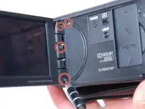
Fold back the hinging panel on the top of the camera located near the lens.
-
Use the Phillips #00 head to remove the following 5.5mm screws on the top under the hinging panel.
-
-
-
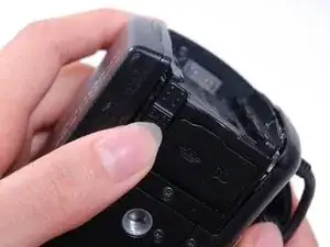
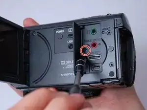
Slide back the cover for the DC and A/V ports on the right-hand side.
-
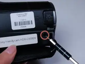
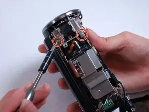
Use the Phillips #00 head to remove the following 5.5mm screws underneath the cover and on the right-hand side.
-
-
-
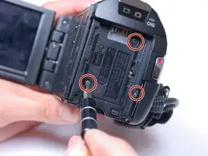
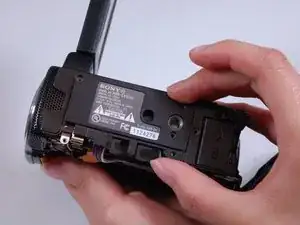
Look at the right side of the camera (the side with the recording button) while holding back the detached casing.
-
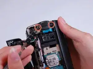
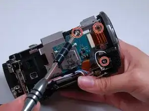
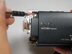
Use the Phillips #00 head to remove the following 5.5mm screws near the recording button.
-
-
-
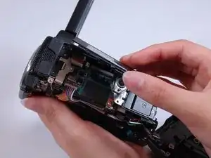
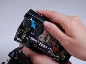
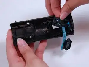
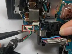
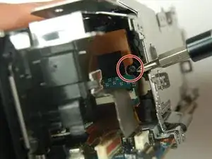
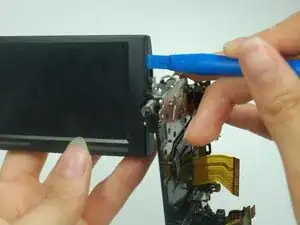
Use the curved tweezers to carefully detach the blue ribbon cable connector from the body of the camera.
-
-
-
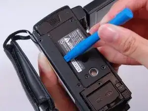
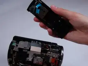
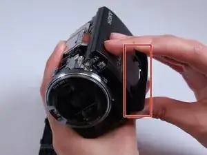
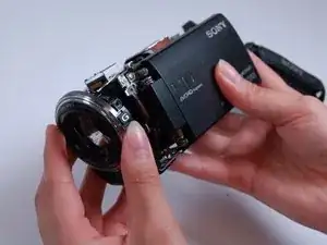
Pull off the top casing by lightly grabbing either side and pulling towards the back of the camera.
-
-
-
Use the Phillips #00 head to remove the following 5.5mm screws on the inside of the top casing.
-
-
-
Use the Phillips #00 head to remove the following 5.5mm screws on the right-hand side near the lens.
-
-
-
Use the Phillips #00 head to remove the following 5.5mm screws underneath the casing strip.
-
-
-
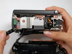
To begin removing the metal casing, use the Phillips #00 head to remove the following 5.5mm screws.
-
-
-
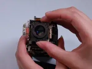
Hold the camera so you can see the motherboard on its bottom.
-
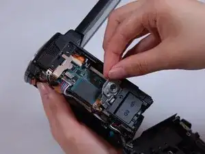
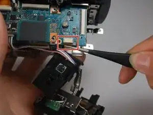
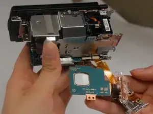
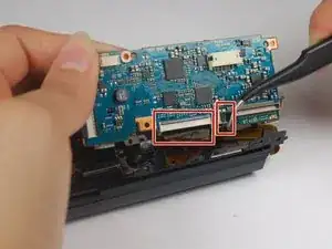
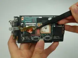
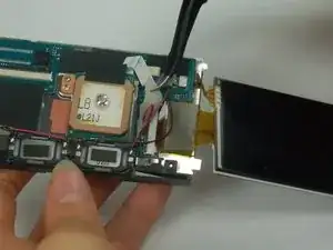
With a pair of straight tweezers, carefully remove the hanging panel by the following bundled cable connectors and ribbon cable connector attached to the motherboard.
-
-
-
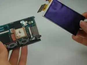
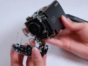
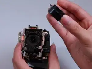
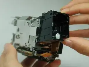
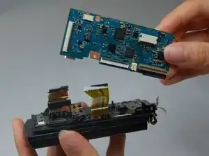
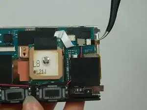
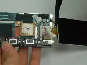
The camcorder's chip and part of the motherboard should naturally fall off at this point and should carefully be removed and placed to the side.
-
-
-
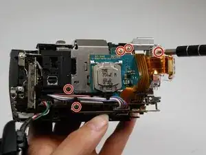
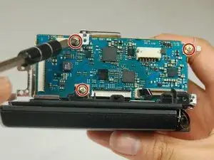
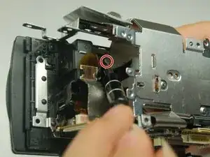
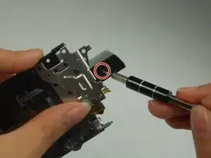
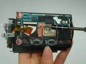
Use the Phillips #00 head to remove the following 5.5mm screws from the side of the motherboard.
-
-
-
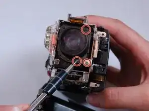
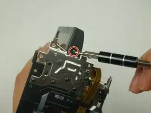
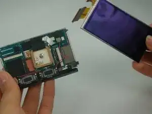
Use the Phillips #00 head to remove the following 5.5mm screws and remove the lens compartment by carefully pulling it out of the metal casing.
-
-
-
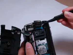
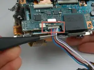
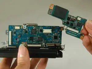
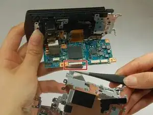
Using a pair of tweezers, remove the ribbon cable connector attached to the metal casing and the motherboard.
-
-
-
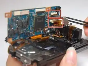
Using a pair of tweezers, remove the following ribbon cable connectors to remove the motherboard from the camcorder.
-
-
-
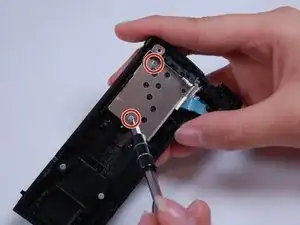
Rotate the display screen to access one of the two 5.5mm screws on the surface nearest to the camera body.
-
Use the Phillips #00 head to remove the screw, then rotate the screen in the opposite direction to access and remove the other identical screw.
-
-
-
Use the Phillips #00 head to remove the following 5.5mm screws underneath the back casing of the screen.
-
-
-
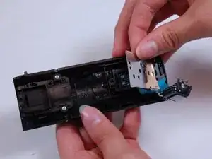
Use the tweezers to peel back the black tape covering the last ribbon.
-
Carefully detach the ribbon cable connector attaching the screen from its back.
-

To reassemble your device, follow these instructions in reverse order.