Einleitung

Use this guide to replace the speakers on a Sony Vaio Tap 21 all-in-one desktop. There are two speakers which are located on the upper corners of the device. They are connected to each other with a red and black cable.

  1. Quy1tiKF2Uen2Tof
    Quy1tiKF2Uen2Tof
    HJjJLWvsNI6hcfFW
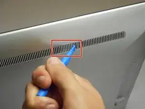
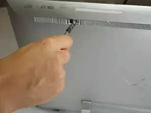
    • Insert the plastic opening tool at an angle into the grill and lift the tab by applying force down and to the left as you are lifting it out of place.

    • Use your plastic opening tool to remove the right plastic tab blocking the screw mounts behind the device.

    • The plastic tab is located on a plastic stretch of grill running along the upper half of the back of the device.

    • You can find the tab looking for a solid fill within the grill. The tab is solid within the slits.

  2. veP4XcPpxk446lCY
    veP4XcPpxk446lCY
    up5hlmuvuUb5cnMa
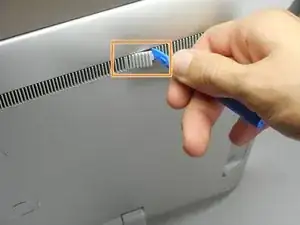
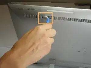
    • Insert the plastic opening tool at an angle into the grill and lift the tab by applying force down and to the left as you are lifting it out of place.

    • Use your plastic opening tool to remove the right plastic tab blocking the screw mounts behind the device.

    • The plastic tab is located on a plastic stretch of grill running along the upper half of the back of the device.

    • You can find the tab looking for a solid fill within the grill. The tab is solid within the slits.

  3. XfLWdsUcHbMCbAaV
    XfLWdsUcHbMCbAaV
    slOysmGsTI4dJisl
    5SHWtIwneyfLTZst
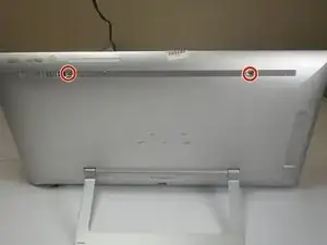
    • Remove the two 5mm screws on the back of the device using a JIS 0 screwdriver.

  4. lXC5vJWwRnEFvFal
    lXC5vJWwRnEFvFal
    OhEaavnXqVi544Ed
    C1TPiImNivTKhbsM
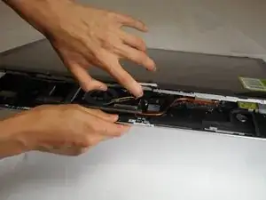
    • Face the screen of the device upwards.

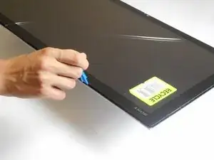
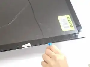
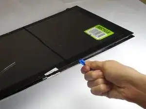
    • Gently un-clip the screen around the four sides of the body with the plastic opening tool.

    • Use an up-down motion.

    • It would be easier to do this if the device is fully rested flat by pushing the device down. It should rest on the stand.

    easy to do with cracked screen

    DANIEL K GIERMANSKI -

    Can that work on bail tab 20

    D gesse -

  5. nKJIpARWnk3WbiCH
    nKJIpARWnk3WbiCH
    Up2asCbmfjXVq31Y
    5MT1aFDnUUxFnudT
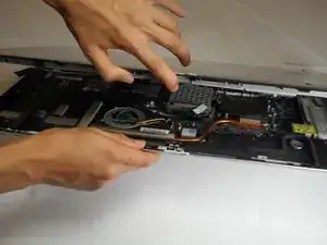
    • Lift the screen gently from the top of the device.

    • Make sure to lift the screen from the same side the screws were removed.

  6. LDDagWFuGewftfMK
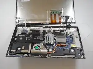
    • Slowly and gently lay the screen on its face.

    • It's important that the cables are not damaged while doing this process. Ensure as you lay the screen on its face any cables are carefully moved insuring no stress is applied on the cables.

  7. k4V61SsPj1LGmLFH
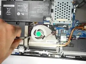
    • Remove four 9mm screws from the fan attachment located on the motherboard with a Phillips #1 screwdriver.

  8. PcNSxDgx1Eh3HS3a
    • Remove two 6mm screws located on both sides of the fan component using a Phillips #1 screwdriver.

  9. 3ODlbhtj4OJpc6Vm
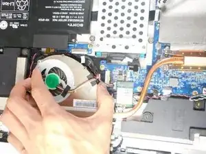
    • Un-click the cables attached to the face of the motherboard.

    • These cables are secured tight in their place so remove them with a firm grip.

  10. PLCcDunxVFNCaFDS
    PLCcDunxVFNCaFDS
    qNpRW2KSukdxdpmN
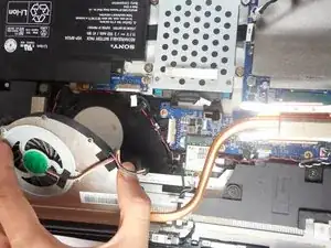
    • Firmly lift the fan from the surface.

    • The fan is held tight in its place so lift it with slightly more force.

  11. kBmENQL2XpmHeuU2
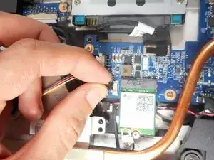
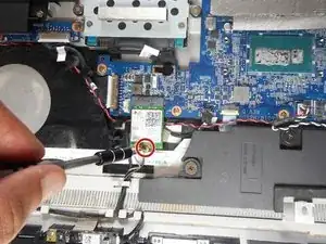
    • Use a JIS 00 screwdriver to remove a 5mm screw from the wireless receiver.

    • The wireless receiver is a chip located in the area between the motherboard, fan, and one of the speakers.

  12. fjr3KJ6PRUcMi4uQ
    fjr3KJ6PRUcMi4uQ
    XmQqXQJtIUprrnBK
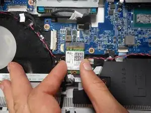
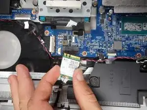
    • Gently detach the wireless receiver and place it somewhere it does not obstruct the speaker assembly.

  13. DVqLFMeGepSEmCtl
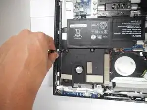
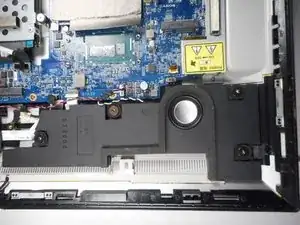
    • Remove a total of four 8mm screws with the Phillips #2 screwdriver from the speaker located below the motherboard.

  14. 4fBbkFMPMBOlqYLW
    4fBbkFMPMBOlqYLW
    IGRhCXEyQZynqKre
    Bly6o4RwVYxlR2Z1
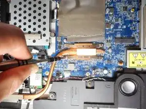
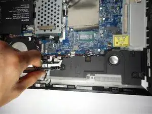
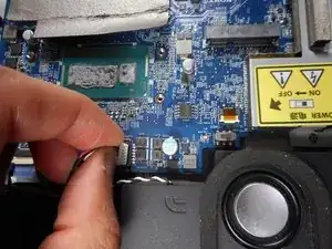
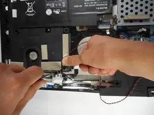
    • Detach the cables that connect from the speaker to the motherboard.

    • The cables attached to the motherboard are held firmly in place so pull them with slightly more force to release them.

  15. XMlv5tTxCIaw1fw6
    XMlv5tTxCIaw1fw6
    DoPNpHDCALvbCNLH
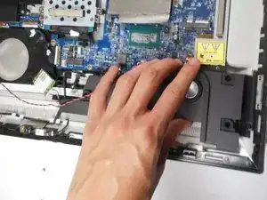
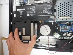
    • Slowly lift the speaker from its base.

  16. hefrro6YwfT3VvXw
    hefrro6YwfT3VvXw
    jsrrUSM1wDwYPJiE
    • Remove four 8mm screws from the speaker below the battery with a Phillips #2 screwdriver.

    • One of the four screws is located under a foam pad on one of the corners of the speaker. Lift the foam pad to remove the screw.

  17. ARMHqFZ5sSPLw2PV
    ARMHqFZ5sSPLw2PV
    mktXFq2fxF1B6AlI
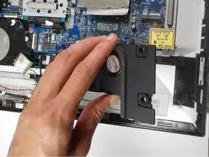
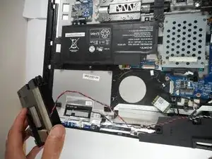
    • Carefully lift the speaker from its base.

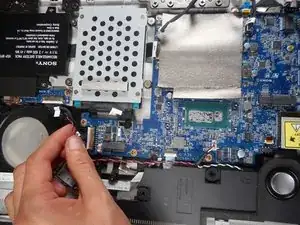
    • To fully remove the speaker assembly, remove the red and black intertwined cables that connect both speakers.

Abschluss

To reassemble your device, follow these instructions in reverse order.
Mauricio Retana

Mitglied seit: 02/10/17

721 Reputation

0 Kommentare