Einleitung

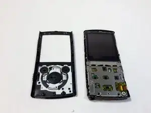
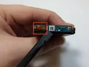
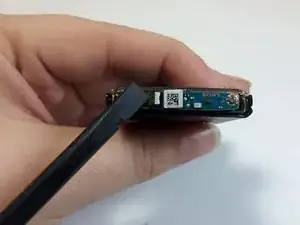
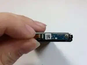
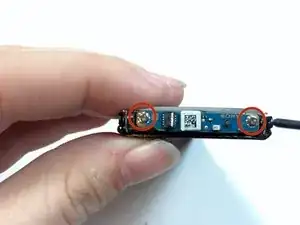
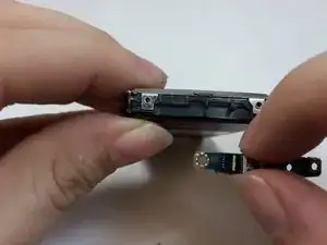
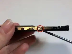
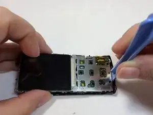
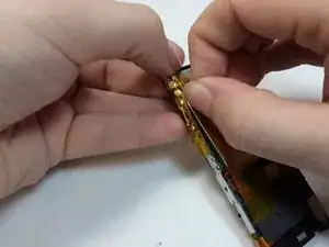
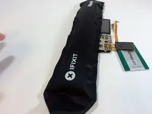
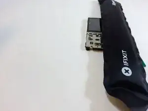
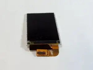
This tutorial will guide you in replacing the LCD display and cover.

  1. pSdpajcdH5KuX42K
    pSdpajcdH5KuX42K
    UVoYIKgBdWfrmDOy
    WOJLI1iGa5TEVCLJ
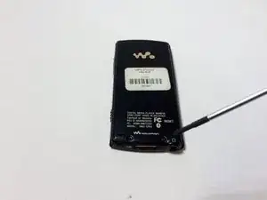
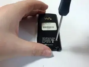
    • Remove the two black 6.4mm Phillips screws from the back of the device.

  2. qNHM6WUJ1JHx2OGl
    qNHM6WUJ1JHx2OGl
    MEF2HQ6IMiTkAkph
    1Enf5jMAxAuoN2xj
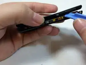
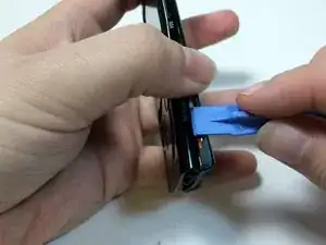
    • Using a plastic opening tool, work your way around the edges of the device, carefully prying off the front panel.

  3. 1UvFvSsR2PcSdkIJ
    1UvFvSsR2PcSdkIJ
    MfxI1LssAUe5NIqX
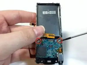
    • Remove the two 2.8 mm phillips screws located on either side of the device near the top.

  4. DKRWC6n2yEZOf6PJ
    DKRWC6n2yEZOf6PJ
    PgbxJcseCOgZrCh2
    • Carefully pull the top piece away from the device.

  5. ec6LqXLDKqOeDcQo
    ec6LqXLDKqOeDcQo
    WFvYNRmRTFE5i4VL
    orWN1mestH1gdcI2
    • Use the flat end of the spudger to flip up the retaining flap for the bluetooth module.

    • Be sure to lift up on the retaining flap, and not the socket itself.

  6. lHRSbghjdyJELRff
    lHRSbghjdyJELRff
    1QJKgeLKWOMfixnU
    CGRJ1PoplThYOvts
    • Remove the two 1.8mm silver Phillips screws on the Bluetooth module.

    • Lift up on and remove the Bluetooth module.

    • The ribbon cable must first be removed in order to access the highlighted screw.

  7. RSiPFKQ1PIfSBjGn
    RSiPFKQ1PIfSBjGn
    Oe3tYEwiumKYNSBx
    wgQFpKwjj5UFWf5O
    • Remove the two 2.8mm silver Phillips screws on the sides of the frame.

    • The two 2.8mm screws are on each side of the device.

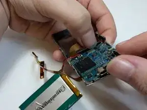
    • Insert a plastic prying tool between the bottom of the case and the motherboard.

    • Pry up the assembly and lift it away from the case.

  8. C6It6WXZvYqmXiNH
    C6It6WXZvYqmXiNH
    L5jSsORtfMxKuOFj
    MMP451pYBueiioVR
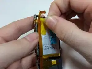
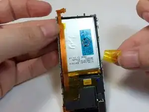
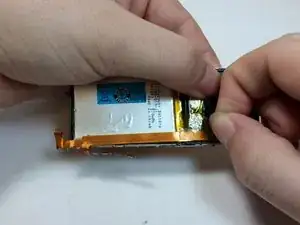
    • Remove the yellow tape from the battery and volume control module.

    • Save tape for reassembly.

  9. gRqx5YFQkcGemPUY
    gRqx5YFQkcGemPUY
    tycHOVSUlu2TRHtM
    hraVlEYGnFvIAPYn
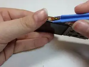
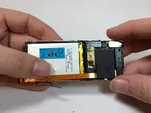
    • Use a prying tool to pry under the volume control module.

    • This module is glued on, using too much force may damage or warp the module.

  10. hRQRNDo2NuNVoCkl
    hRQRNDo2NuNVoCkl
    kjB6xNUNJvh2pWJC
    gKcENdytUQvLaAqS
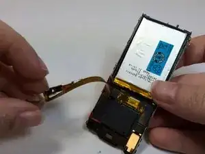
    • Remove the tape from EMF shield and the LCD housing.

    • Lift up on the volume control ribbon.

  11. tUbpWKrh3afsiLmL
    tUbpWKrh3afsiLmL
    QqB6qDTryuQ4eLZl
    oIHaevUiftLeLtFR
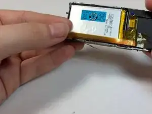
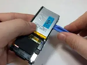
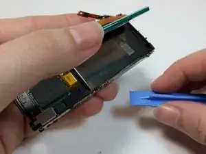
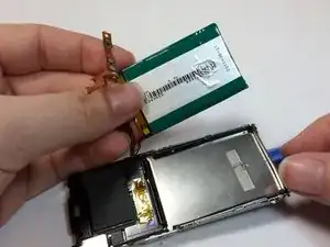
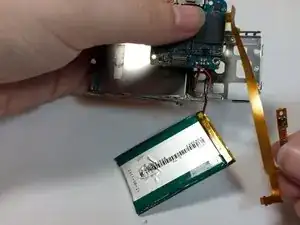
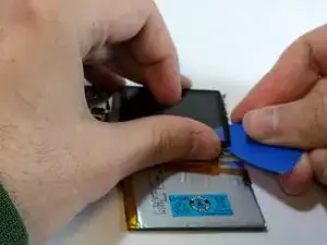
    • Insert a plastic opening tool under the battery and lift up to remove it.

    • The battery is glued on, too much force may damage the battery casing.

    • The battery is soldered to the motherboard, care should be taken to not place too much stress on the wires.

  12. p1WbeOGCTXsF4xEG
    p1WbeOGCTXsF4xEG
    KYIXrXbdKFV21Nc2
    sJYDwjyIRyKEann5
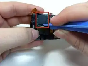
    • Remove the black shielding tape from above the Hard Drive.

    • Peel the foam cover away from the hard drive.

    • Use a plastic opening tool to remove the EMF chip from the motherboard.

    • The hard drive is soldered onto the device. Be careful not to pull too hard on the hard drive.

  13. FXkcw6ysm2jN1DMS
    FXkcw6ysm2jN1DMS
    2yHPjeBaGJCcqqkv
    aZbilXejb56WA3BB
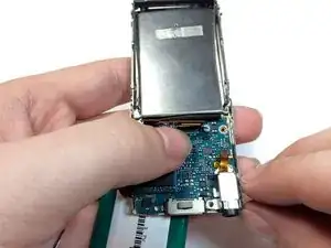
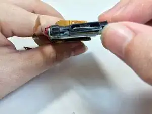
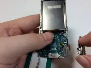
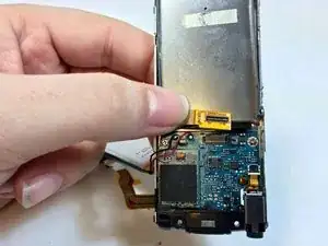
    • Remove the plastic bracket by pushing up with your thumb to expose the display connection.

  14. G2D2lwjJrsTrncCF
    G2D2lwjJrsTrncCF
    feFa5Ov225o5ZMjA
    uH1TSwvSrkwg1Ggj
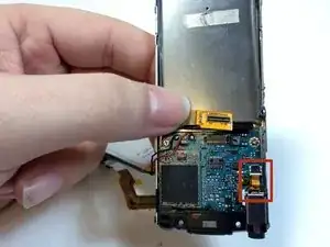
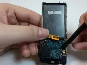
    • Use the flat end of a spudger to flip up the retaining flap on the audio jack module.

  15. QSrOKgb1U1SuWXLo
    QSrOKgb1U1SuWXLo
    rNBeT3Vmif1dXDa5
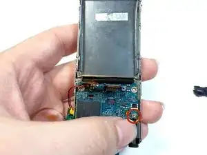
    • Peel back the ribbon for the audio jack and remove the 1.8mm silver Phillips screw.

  16. uEHsYS1bckSMIGgS
    uEHsYS1bckSMIGgS
    DB2PyfWOmkagmDyE
    rTNwpNZU1WZledrc
    • Remove the mic casing by pushing up and in.

    • Remove the headphone jack and the bottom casing.

  17. YamjtM3MKZ1FXDgn
    YamjtM3MKZ1FXDgn
    4mQSNVQ5gwOIanbP
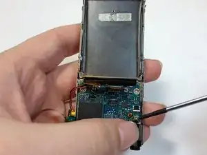
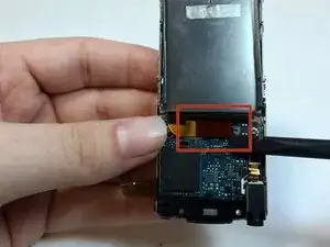
    • Use the prying tool to remove the LCD ribbon wire.

  18. L5lcYPYRKRiKpcu6
    • Lift up on the LCD ribbon and remove the two 1.8mm silver Phillips screws.

  19. ZktGXZO2OgJFM6yK
    ZktGXZO2OgJFM6yK
    MsKUoKlmw2AXRZg6
    T1xFNG4pKHKkbJmd
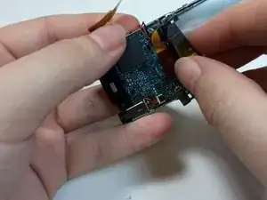
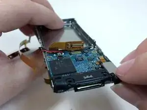
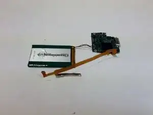
    • Lift the motherboard away from the frame with your thumb to remove it from the device.

    • Pull the volume control module through the space in the frame.

    • If you are using the magnetic project pad or other magnetic surface to keep your screws, do not place the hard drive on or near the magnet.

  20. 4eZdU4XROaldJLm6
    4eZdU4XROaldJLm6
    efvLYOCkdaq3JwtY
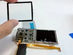
    • To remove the LCD display cover, first melt the glue with the iOpener tool.

    • For more detailed instructions on how to use the iOpener, see iOpener Instructions

  21. TxAnhSanNhZtTGEa
    TxAnhSanNhZtTGEa
    NbPQMQSbQLnpJ4Lh
    5utUh6jACJm1KIuA
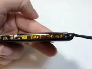
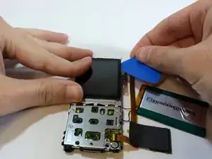
    • Carefully slide the iOpener wedge tool under the edge of the LCD display cover to separate it from the device.

    • Slide the wedge under all edges of the cover.

    • Once all of the glue has been broken, you can pull up on the cover to remove it.

    • The flat side of the spudger tool also works for this step

  22. WmkSduCEXc6nBh2e
    WmkSduCEXc6nBh2e
    E3QCIaxBpmBEaimA
    R6KSAykIR1IPYjJL
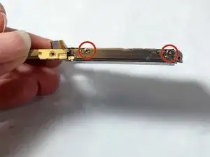
    • Remove the two 1.8 mm Phillips screws from both sides of the frame.

  23. xRSufJyJnhHRNV3v
    xRSufJyJnhHRNV3v
    rHYGCnCkJtJLF6Ul
    uOEvnITZUeJITeWB
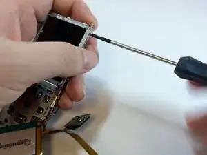
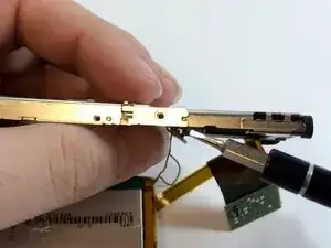
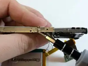
    • Use a strong pry tool to lift the metal brackets away from the device. You will need to bend the metal slightly to remove it from the dimples.

    • This step will require slight force to separate the frame. Do not bend the brackets too far so that they can be replaced later.

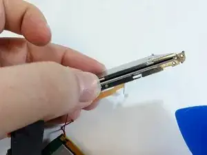
    • Once separated, pull the innermost frame containing the LCD display away from the brackets.

  24. vqrpqSRO2RiBteIZ
    vqrpqSRO2RiBteIZ
    kvqVbMAqreZkeJvt
    mieCX5jmaK6shAEP
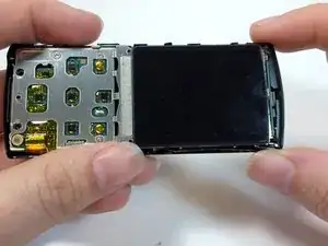
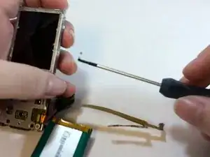
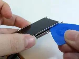
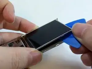
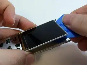
    • Slide an opening pick under the LCD display to separate it from the rest of the device.

    • The pry tool also works for this step.

  25. tYYbVEMxxrdKCpsf
    tYYbVEMxxrdKCpsf
    YDwCs16qhk4UDqhU
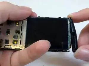
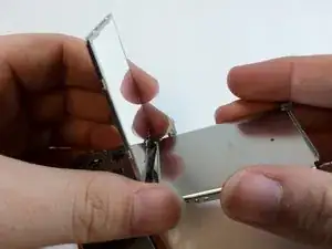
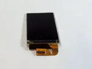
    • Lift the LCD display off of the frame to remove it from the device.

Abschluss

To reassemble your device, follow these instructions in reverse order.
Matthew Olson

Mitglied seit: 21/01/15

167 Reputation

0 Kommentare