Einleitung

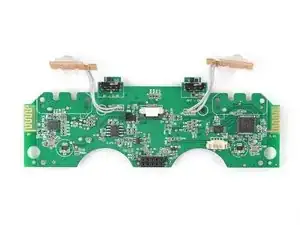
Use this guide to remove the mainboard in your SteelSeries Stratus Duo controller.

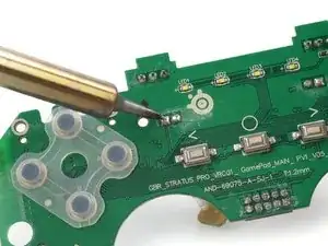
A completely removed mainboard simplifies desoldering parts like the trigger buttons.

  1. DEitlsRW1ZEqvXAX
    DEitlsRW1ZEqvXAX
    GPL1htALS3WrfPrI
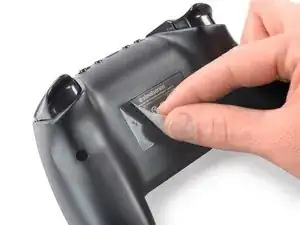
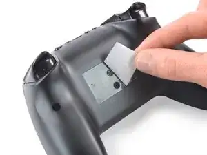
    • Use your fingers to remove the sticker located on the back cover of the Stratus Duo.

    • If you have trouble removing the sticker, heat an iOpener and apply it to the rear case for two minutes to loosen the adhesive underneath. You can also use a hair dryer to soften the adhesive.

  2. yYOv3pVcAAsfITRv
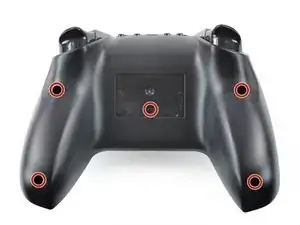
    • Use a Y0 Tri-point screwdriver to remove the five 9.3 mm-long screws securing the back cover.

  3. vgAv6AWkhn31BpC1
    vgAv6AWkhn31BpC1
    U1yyKvYwWhOEoWZC
    mA56JBnMSefWUs4P
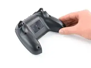
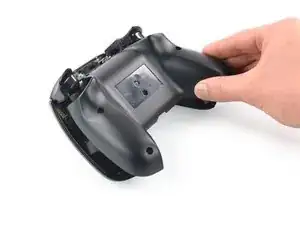
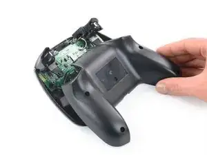
    • Don't try to remove the back cover assembly all the way yet, as it's still connected to the mainboard.

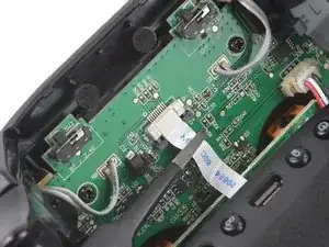
    • Carefully lift the back cover assembly away from the frame and move it downward to uncover the battery cable and the interconnect cable at the top of the motherboard.

  4. GSD1uHYYKShBmRlR
    GSD1uHYYKShBmRlR
    lVDZNWf1mhSt2Njh
    vHxWAhPsBvQFUd1V
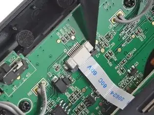
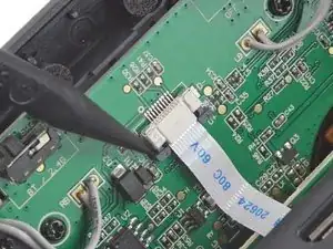
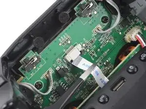
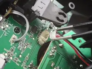
    • Using the pointed end of a spudger, push the grey tabs on the interconnect socket away from the socket, parallel to the interconnect cable, to release the cable.

  5. dtuKMIvfjIcxhMBX
    dtuKMIvfjIcxhMBX
    BNvarcllVYDdhSPA
    • Use a pair of blunt nosed tweezers or your fingers to pull the cable out of the socket.

  6. xaAmxStDcpSal3QY
    xaAmxStDcpSal3QY
    DjAiPhOlMahXRZFv
    ElJWZvtglfmQYKKw
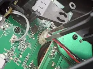
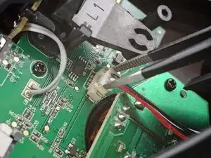
    • Use a pair of blunt nose tweezers to grab and lift the connector away from the motherboard.

  7. ahHyoQQroZHZSjjU
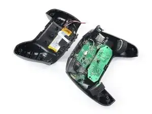
    • Remove the back cover assembly.

  8. Q6TiWLVqrIZP1ujF
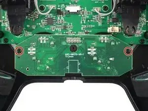
    • Use a Phillips screwdriver to remove the two 6.8 mm-long screws securing the thumbsticks board.

  9. ahIGKqMrH1qcSBqn
    ahIGKqMrH1qcSBqn
    3BWtS5qciJeBwMr5
    ZRpiYXgjfDJFJRAZ
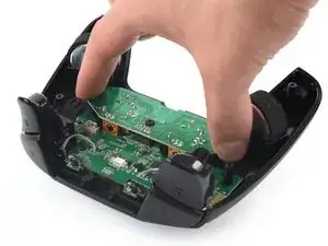
    • Grab the thumbsticks board with your hand and disconnect it by pulling it straight up and out of its socket on the mainboard.

    • Remove the thumbsticks board.

    • For reassembly make sure to correctly align the ten pins with their socket on the mainboard.

  10. oVax6mstCkwSZgSr
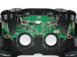
    • Use a Phillips screwdriver to remove the four 6.8 mm-long screws securing the mainboard assembly to the case.

  11. SODEgtuwXWdCoanM
    SODEgtuwXWdCoanM
    q5oEeDTN1WBN2X5l
    DCJXWILo4dAiZpVX
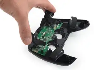
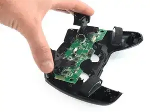
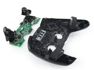
    • Use your hand to remove the mainboard assembly by tilting it out of the plastic cover.

  12. c5IUYKU4d1ETGrsN
    • Use a Phillips screwdriver to remove the four 7.2 mm-long screws securing the trigger button covers to the mainboard.

  13. bXXRqXNSxABEKJlT
    bXXRqXNSxABEKJlT
    AIsrO1iLRFitpnvc
    Qa4HlfiGOVMtPKZv
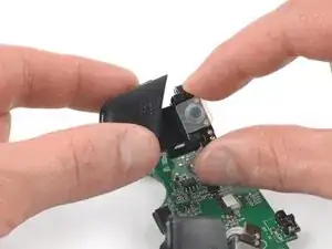
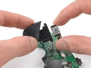
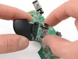
    • Use your fingers to pull the trigger button covers off of their shoulder button breakout boards.

  14. SGRhCPFgBUOTJUne
    SGRhCPFgBUOTJUne
    sxfijOiHLAWM5oSu
    VDB5hndUCLLOYIgO
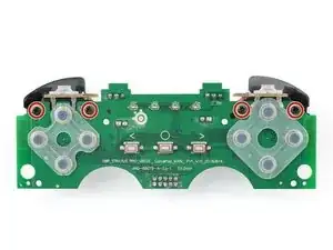
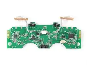
    • You are left with the mainboard.

    • If you replace the mainboard, compare it to the new one. You may need to transfer over some components, e.g., the rubber pads for the D-pad and the action buttons, or even desolder the shoulder button breakout boards.

Abschluss

To reassemble your device, follow these instructions in reverse order.

Take your e-waste to an R2 or e-Stewards certified recycler.

Repair didn’t go as planned? Check out our Answers community for troubleshooting help.
Adriana Zwink

Mitglied seit: 18/12/19

38806 Reputation

0 Kommentare