Einleitung
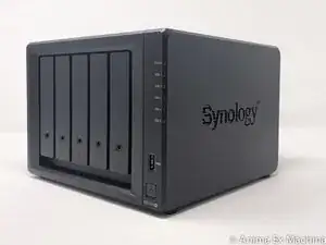
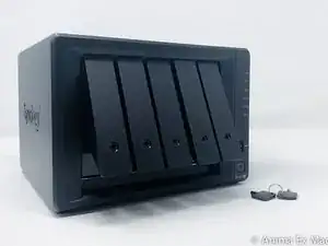
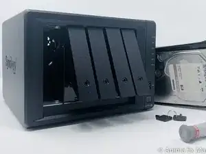
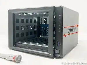
Here's a step-by-step tutorial to dismount DS1019+ NAS until you reach the motherboard.
'Note: the interest of this tutorial is however limited.'
Indeed, most of the components that a user can be brought to add or change are now accessible directly, without disassembly (storage disks, memory expansion, SSD cache).
This is a step forward since, for example, a DS415 + / DS916 + must be completely removed to change a single RAM array.
Only the memory stack on the motherboard and fans remain inaccessible directly and require the disassembly of the NAS described in this tutorial to be changed (whether they are HS or replace them not the best).
The dismantling time is estimated at one hour (a single experiment on the timer). That said, it is certainly achievable in 20/30 minutes.
The photographs were taken with an iPhone Xr, un trépied SIRUI T-025SK, using a portable LED studio.
nota : le résultat est acceptable, mais en régression niveau qualité (manque de temps pour traitement des photos et qualité focus / netteté).
Werkzeuge
-
-
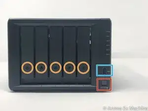
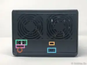
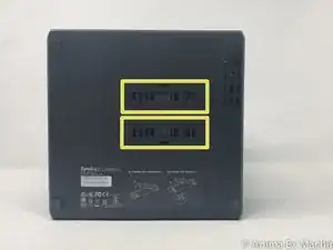
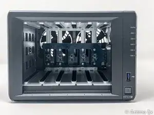
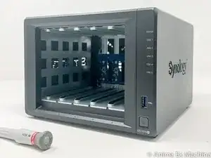
Here are the different interesting faces of the case: front (bay disks), rear (connectors and fans), below (2 hatches SSD).
-
FRONT : disk cage lock / REAR : Kensington security incision (K-lock)
-
2 USB 3 ports (1 in front and 1 behind)
-
2 x RJ45 Gb ports.
-
FRONT : 1 port for power supply
-
BELOW : 2 M.2 NVMe 2280 ports (disk cache)
-
REAR : 1 eSATA port
-
-
-
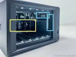
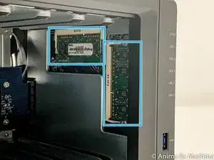
This is a significant innovation, the memory is now directly accessible and without disassembly of the housing, for the original bar as for the extension port.
-
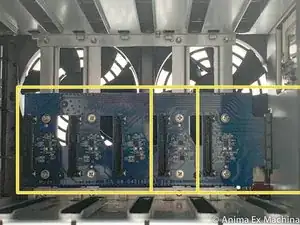
backplane with 5 SATA connectors
-
2 memory slots
-
-
-
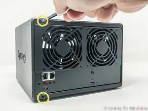
Remove the 2 screws on the back of the case at the top and bottom (not the one above the USB port)
-
-
-
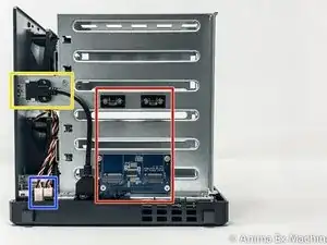
in red: SSD M.2 expansion card 2280
-
in yellow: USB 3 port
-
in orange: internal connectors of the 2 fans
-
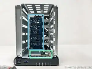
in green: 2 slots of RAM
-
in blue: SATA III backplane (5 hard drive bays)
-
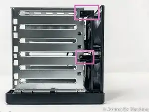
in pink: fixing the fans on the chassis
-
3-PIN connectors of the fans
-
-
-
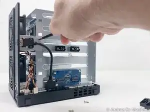
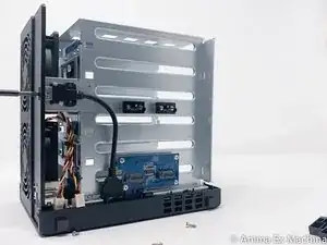
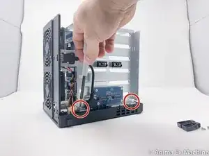
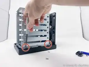
Remove the 2 screws from the holding plate of the USB connector 3 and on the rear side.
-
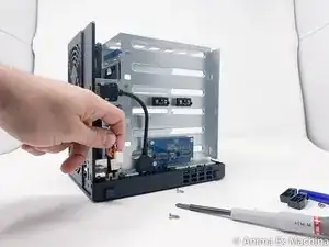
Then remove the USB3 metal plate.
-
-
-
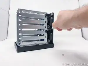
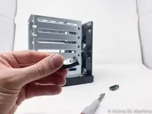
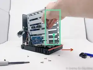
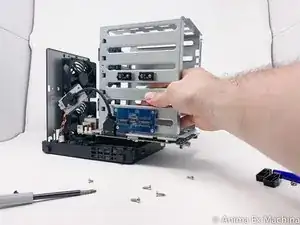
Remove the motherboard from the case paying attention to the USB 3 connector on the front and the power button. To do this, move the front panel a little and lift the motherboard upwards (outside).
-
-
-
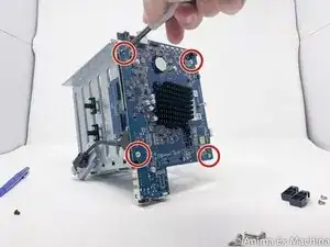
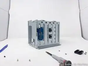
Once the motherboard is out, unscrew the 4 screws of the metal protective cover (metal plate).
-
-
-
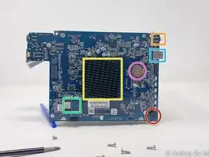
Motherboard processor side
-
INTEL Celeron J3455 / 64-bit / Quad core 1.5 burst up to 2.3 GHz
-
Memory battery
-
Internal beep
-
USB 3 port
-
Power button
-
Flash memory
-
-
-
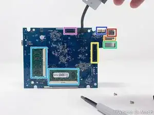
Memory side of the motherboard (pre-equipped with 8 GB of RAM)
-
NVMe M.2 SSD expansion card connector
-
Connector (PCIe ??) for SATA disk expansion card
-
Fan connector (x2)
-
Power connector
-
RJ45 LAN Connector x2
-
eSATA connector
-
2 x 4GB DDR3L 1866 RAM Memory Stick
-
To reassemble your device, follow the instructions in reverse order.
