Einleitung

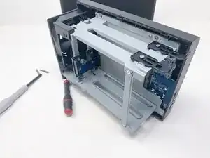
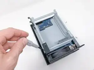
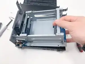
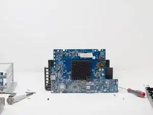
Here's a step-by-step tutorial to dismount each piece of the NAS until you reach the motherboard.

This NAS integrates 2 Go of soldered memory, an INTEL Celeron J4025 64-bit two-core processor, two slots for SATA drive (HDD or SSD) 2,5" or 3,5".

'Note: the interest of this tutorial is however limited.'

Indeed, most of the components that a user can be brought to add or change are now accessible directly, without disassembly (storage disks, memory expansion).

The BIOS battery, and the fan remain inaccessible directly and require the disassembly of the NAS described in this tutorial to be changed (whether they are HS or replace them not the best).

The dismantling time is estimated 15 (a single experiment on the meter). That said, it is certainly achievable in 10 minutes.

The photographs were taken with an iPhone Xr, using a portable LED studio.

FACOM screwdrivers have been used. Becarrefull the screws are not cruciform anymore …

  1. pCAOi33O42DVEuun
    pCAOi33O42DVEuun
    bhASbUBiDsuQrqOJ
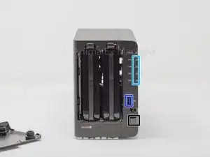
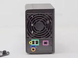
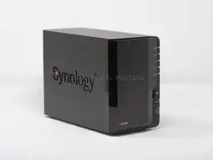
    • Here are the different interesting sides of the case: front (disk bay, LEDs), rear (connectors and fans).

    • power button

    • 2 x RJ45 Gb ports

    • Disk and system activity LEDs

    • Kensington security slot (K-lock)

    • 1 x power supply port

    • 2 x USB 3 ports (1 front and 1 back)

    • 1 x reset button

  2. ZlIxPp6fWUxyAtP1
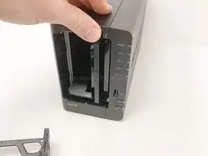
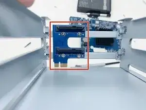
    • nothing complicated ... remove the cage from the SIN while pressing the push button

  3. IOnAgel4delD4MAF
    IOnAgel4delD4MAF
    56CTwY1KMfvTiQVY
    lbSBo4BEDOyR1Rxm
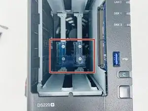
    • 2 x SATA port

    • Only the empty memory slot is accessible.

    • Evolution since v2018: internal memory (2 GB) is soldered on board.

  4. 1MHRGVBP6cET3Efo
    1MHRGVBP6cET3Efo
    TcGCkwGtOX4bPC3c
    5qDyPANDugGCs3oZ
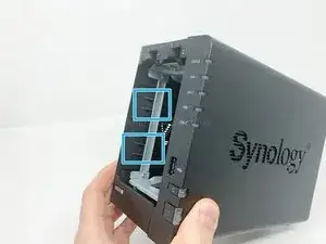
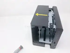
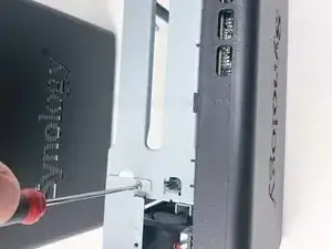
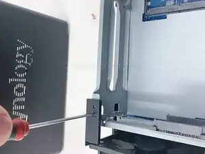
    • Use a screwdriver (flat tool) to unlock the two plastic lugs.

    • These are two locking notches (on the front, left side) to be "unlocked" or "unlatched".

    • Be careful not to bend the metal bar.

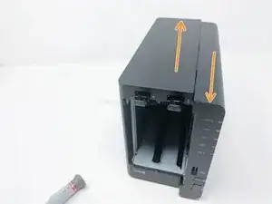
    • then slide the two parts of the shell parallel to each other, as shown in the pictures.

    • then separate the two parts from each other perpendicularly.

    • the removal of the rear screws (fan, plate) is not mandatory ...

  5. AVMuuCxssLLuTkCq
    AVMuuCxssLLuTkCq
    CK5XwOgBtRStpjkY
    xZSUfXH5tAjvVXol
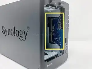
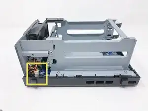
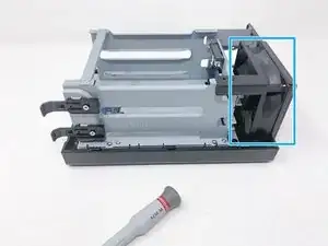
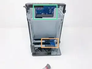
    • orange : internal SATA ports

    • yellow : fan connector

    • blue : fan

    • green : free memory slot

  6. FN5sVkIZbPVfsUhW
    FN5sVkIZbPVfsUhW
    VBdVgA2DY5jfTDEC
    • simply unscrew the screw to remove the spacer.

    • You will notice the guides for positioning the spacer.

  7. 1LBNs3dt2jvfXYao
    • same as above ... unscrew the screw to remove the plastic spacer

    • you will also notice the markers ...

  8. WhOQkFM4W3UpCTNp
    WhOQkFM4W3UpCTNp
    oq1bZVlEGKN1Pptr
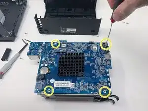
    • to remove the motherboard from the case, unscrew the 4 screws as follows ...

    • There are 4 x screws to fix the metal support of the motherboard. 4 x screws to fix the motherboard to the metal support. And finally 4 x screws to fix the disk bay cage to the metal support of the motherboard. Pay attention!

  9. Q5piZMAOqIaKA1O5
    • once the screws are removed, pull the front panel (at the USB port) slightly outwards ...

    • This allows the connectors to pass through.

    • then lift up the motherboard with the disk cage.

  10. 6bKDQ6yg4dWZJ4EW
    6bKDQ6yg4dWZJ4EW
    kooysDLnZFvdpUxt
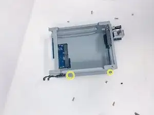
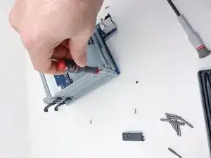
    • remove the yellow marked screws (x4)

    • no specific photographs ... nothing very complex!

    • This step is not mandatory to access the motherboard

  11. S3qYsXMFYnjmSEPL
    • Remove the yellow marked screws (x4)

  12. HwVVeWygobHDyS1E
    HwVVeWygobHDyS1E
    JbCtuHbkAXp1No6O
    iq1WhSFA4RT5LUk2
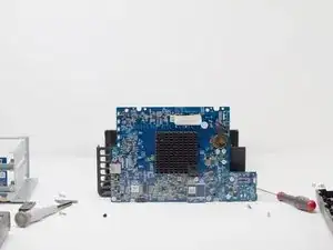
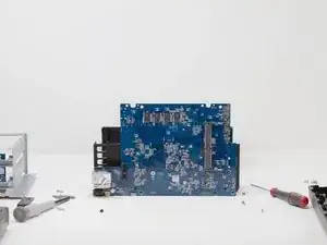
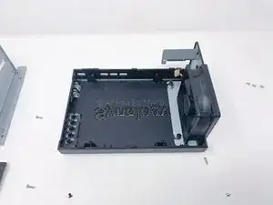
    • 1 - motherboard on the processor side

    • 2 - motherboard memory side

    • 3 - empty case

  13. CJLk4JKodUfLfsQI
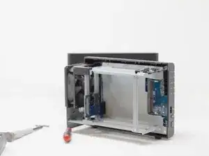
    • Photograph showing one of the phases of dismantling the NAS.

Abschluss

To reassemble your device, follow the instructions in reverse order.
Sébastien

Mitglied seit: 14/12/15

3571 Reputation

0 Kommentare