Einleitung

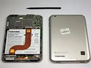
After removing the battery and motherboard, you must disassemble the bottom end of the tablet in order to gain access and disconnect the screen.

  1. XONIBfQx2WMHGXsA
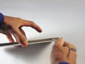
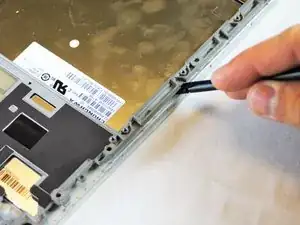
    • Use the metal spudger to create a gap between the back cover and the device.

    • Be gentle when using the metal spudger so that the casing is not damaged.

  2. S3dCNFhyYjcfR3iQ
    S3dCNFhyYjcfR3iQ
    2UOcrwDkTQaTZKj2
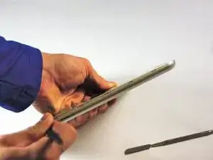
    • Use the nylon spudger to completely separate the back of the device.

    • Take the nylon spudger around the outside of the device cover until it comes free.

  3. KKny4l2SZvXTDjBa
    KKny4l2SZvXTDjBa
    yXCJDKML46D1E1fE
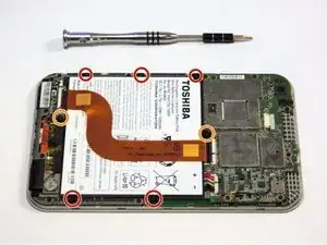
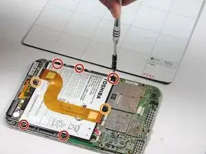
    • Use the Phillips head PH0 to remove the 7 battery screws.

    • The 5 side screws measure 3.5mm.

    • The 2 top and bottom screws measure 4.5 mm.

  4. VlwGjvEDGgRpkRGd
    VlwGjvEDGgRpkRGd
    OhtOyvr3f6YvxrwJ
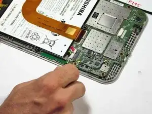
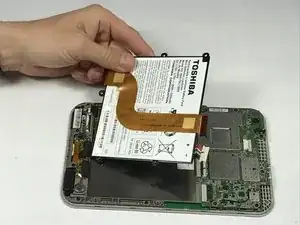
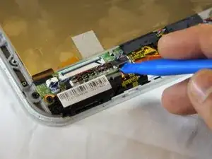
    • To disconnect the cable, use the fine tweezers to flip up the small retaining flap. Then, you can safely pull the ribbon cable out.

    • Be sure you are prying up on the hinged retaining flap, not the connector itself.

    • The zero insertion force (ZIF) connector is used to secure delicate ribbon cables, such as this trackpad cable.

  5. CtSClVdhuJhgeuvw
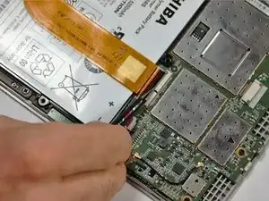
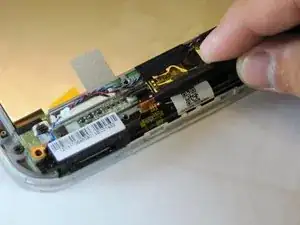
    • Remove the colored power cable from its connector.

    • To disconnect it safely, use the pointed tip of a spudger to carefully push on each side of the connector.

    • Alternating from one side to the other, gently “walk” the connector out of its socket.

    • Be sure to be very gentle when prying colored wires from motherboard to ensure that there is no damage.

  6. myDZIQFIHYttgTBD
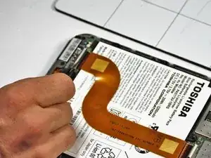
    • Battery will lift out of the device.

  7. vJIAQQqeEtoFddlI
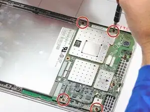
    • Remove the 4 – 4.5 mm screws from the motherboard assembly.

  8. ZrLWGTAjIGqoJQmK
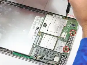
    • Remove the 2 – 3.5 mm screws from the motherboard assembly.

  9. MEmymdGtNxbnGj26
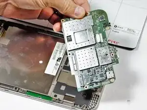
    • The motherboard should come free at this point.

  10. HFVHjHpUeBqsFMhj
    HFVHjHpUeBqsFMhj
    PdHhCVEnZFU12CUK
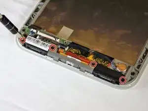
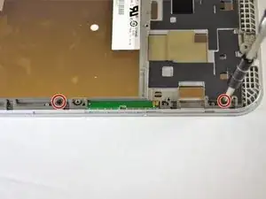
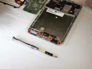
    • Use the screwdriver to remove the 4-3.5mm screws on the two lower speakers.

  11. xF35fGEHKcfE3TTt
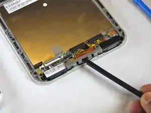
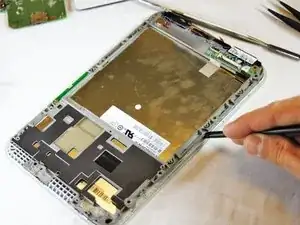
    • Using the spudger, gently pry up on the reinforcement bar and remove from the frame.

  12. RHnvQSK6apAReuGX
    RHnvQSK6apAReuGX
    XnOt6UVWMnQADFIe
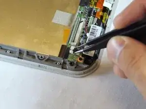
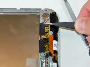
    • Use the fine pointed tweezers to carefully remove the 2 no-fuss speaker connections.

  13. NZdgcndmjhaUsHce
    NZdgcndmjhaUsHce
    YdU2cmovxr5VGM5i
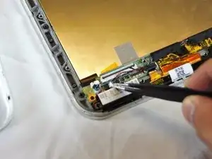
    • Lift the black ZIF connector holding down the ribbon cable with the plastic opening tool.

    • Gently use the spudger to remove the ribbon cable.

  14. jLWGpxLIlDsWBPcN
    jLWGpxLIlDsWBPcN
    ueOAVF2g25DRorcu
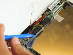
    • Use the fine pointed tweezers to pull the 2 pieces of fabric tape from the lower board.

    • Move the speaker wires out of the way.

  15. xMo5GMhiVKt6sTPp
    xMo5GMhiVKt6sTPp
    KSIgWoQcjOOTYuy2
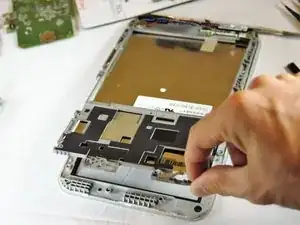
    • Use the plastic opening tool or spudger to gently lift up on the middle logic board and remove it from the frame.

    • This board controls the touch sensors on the front glass.

    • This may require some extra force to loosen up the glue under the board. Make sure to apply force evenly around the edges.

    • The Touch control board has fragile ribbon cables. Make sure to not twist or rip these cables while separating it from the frame and working around the board.

  16. v6OAbMn5Oow1kG5f
    v6OAbMn5Oow1kG5f
    HHurkFaAA1fGhmf2
    kkUMjqjL45gJpUAA
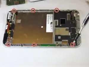
    • There are now 7-3.5mm Phillips head screws holding the frame to the front glass of the tablet.

    • Use the Phillips head screwdriver to remove the 7 screws.

    • The 7th screw is under the touch control board in the bottom middle that we just pried up.

  17. 66uTjVEei6TNhJOH
    66uTjVEei6TNhJOH
    sUY1ttqkNK2niDDO
    vDPpDqQMjoG6GGR6
    • Use the spudger to pry your way around the frame and separate it from the front glass.

    • Be gentle when prying. There are fragile plastic clips and parts that could easily snap with too much pressure.

  18. wVZnJ1pHVFrcYQkL
    wVZnJ1pHVFrcYQkL
    XIKIco2MpGFZnSeF
    • When the frame is separated and loose, Lift from the top and pull the frame off the front glass, setting the glass aside.

  19. Eco4gPeuC6UYw5Pa
    • Remove the lower speakers and set them aside.

  20. CPWWlKCJgNirMn4x
    CPWWlKCJgNirMn4x
    WBofNev4ieDEWLWR
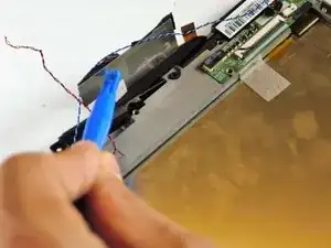
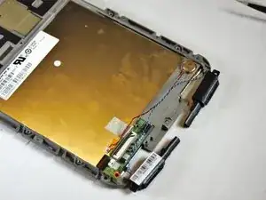
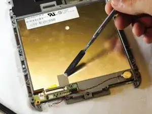
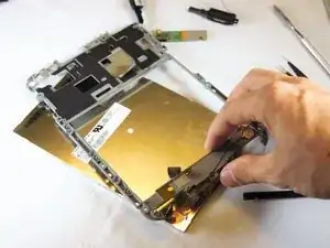
    • The screen is held to the frame with metal fabric tape at the top and bottom of the frame.

    • Use the metal spudger to peel the tape off the back of the screen.

  21. WVF2FyNc3ClbSNIQ
    WVF2FyNc3ClbSNIQ
    Ll1NcYgHMAZNgFUO
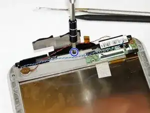
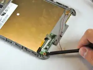
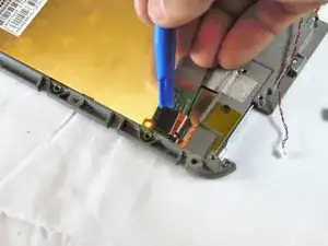
    • The last board we have to worry about is the board that holds the ribbon cable connector (from the battery removal step) and the screen connector.

    • Use the spudger to gently pry up on the bottom side of the board, as you did when removing the touch screen control board.

    • You have to make sure to loosen up the glue underneath and the board should come free from the frame.

  22. YlgSdAZbBcBDfZ1m
    YlgSdAZbBcBDfZ1m
    PjA5DYfcsHNla2jP
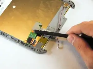
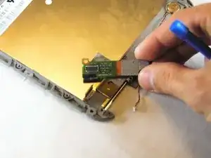
    • Use the plastic opening tool to disconnect the screens ribbon cable from the board by prying up on the flat topped connector.

    • The board will come free and you can set it aside.

  23. oOxXBFBImDp2kjsY
    oOxXBFBImDp2kjsY
    W6eJTXXaU1lY2knU
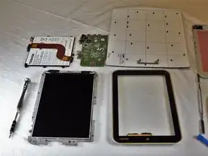
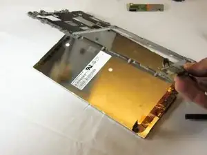
    • With the tape peeled back, and the board disconnected and removed, you can take the frame off of the back of the screen.

    • Your screen is now ready to be replaced with a new one.

Abschluss

To reassemble your device, follow these instructions in reverse order.

Zach Cossey

Mitglied seit: 20/09/16

360 Reputation

Ein Kommentar

How many pins does the screen have? because im planning to replace mine with a new one
johneilasi.ece -