Einleitung
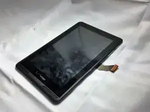
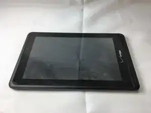
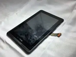
This guide will require prying tools to get the tablet open, a Phillips #00 screwdriver, tweezers, and a spudger. This guide would be invaluable in replacing a broken screen for continued use of the Verizon Ellipsis 7. This guide will require extra precautions, as you are going to have to take out the main motherboard and scrape tape not designed to be removed. Performing the actions in this guide incorrectly could break your device.
Werkzeuge
Ersatzteile
-
-
Hold down the power button until the screen goes black to turn off the device.
-
Remove the SIM card from the device to prevent damage.
-
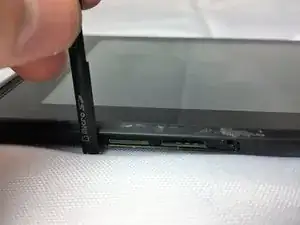
To remove the SIM card, open the SIM card cover on the side of the device.
-
Push SIM card in and pull it out after hearing a click.
-
-
-
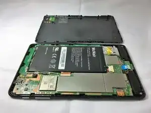
Take off the back panel.
-
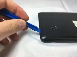
Pry open the back cover carefully with a plastic opening tool.
-
Use the opening tool to disconnect the cover completely. Do not attempt to pry the back cover off with your hands.
-
-
-
Remove the charging (micro-USB) port.
-
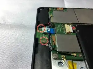
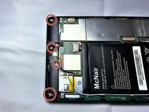
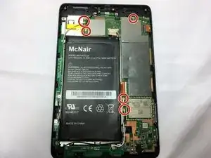
Unscrew the indicated screws using the Phillips #00 screwdriver.
-
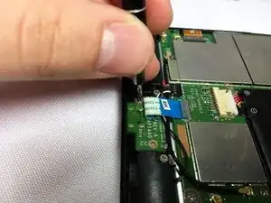
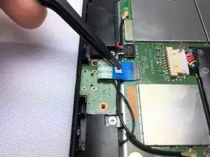
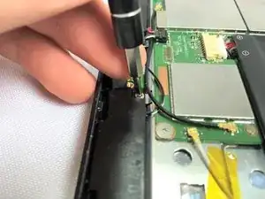
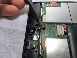
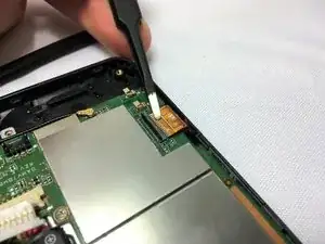
Disconnect the ribbon cable connecting the charging port board to the motherboard using tweezers.
-
Use the tweezers to grab the sides of black, plastic connector. Do not grab from the wires or try to wedge it out from the bottom.
-
-
-
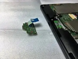
Remove the charging port board from the phone using tweezers.
-
Place the replacement charging port into the phone.
-
-
-
Using tweezers carefully lift the connector up to disconnect it from the motherboard.
-
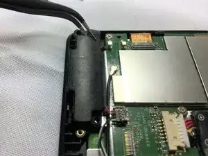
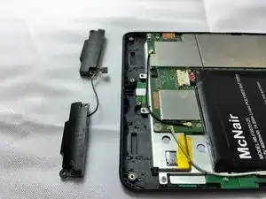
Using tweezers carefully pull the speakers up and out of device.
-
-
-
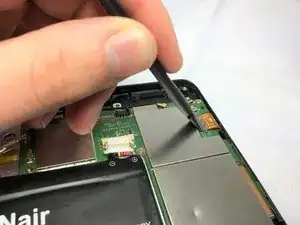
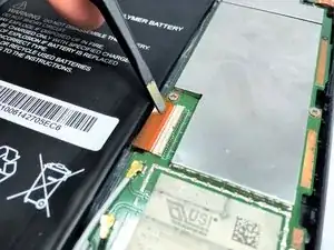
Disconnect the two ZIF connectors that are connected to the motherboard with a spudger. Lift up the metal part of the connector and then pull the connector off of its port
-
Once disconnected pull away from its connector carefully with tweezers.
-
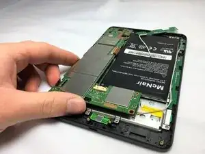
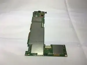
Once the connectors have been disconnected you can gently lift up on the motherboard to remove it from the device.
-
-
-
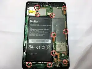
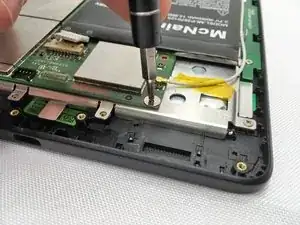
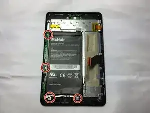
After you remove the motherboard, remove the other two boards by unscrewing the 4 screws with a Phillips #00 screwdriver.
-
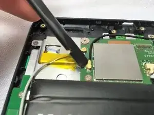
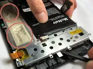
Remove the tape section of the sheet metal plate with the flat end of a spudger.
-
To reassemble your device, follow these instructions in reverse order.
6 Kommentare
Applause for the person for uploading this repair.
should go one step further and include digitizer replacement
ok, so to remove the screen from the frame (for digitizer replacement) i set the heat-bed of my 3d printer to 80c, placed the front bezel with screen and digitizer glass side down on the heater and let it sit for about 2 min.
at that point the perimeter glue was soft enough that i could carefully go aroung the lcd with a sharpened gift card and slowly work it away from the glass and frame.
once the lcd is out (hopefully not broken) i used the same method but with a bit more gusto in order to remove the digitizer from the plastic bezel.
revers steps for reinstall.
