Einleitung
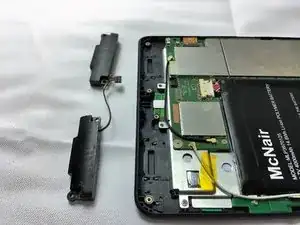
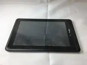
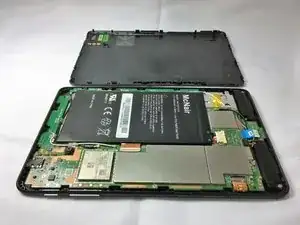
This guide will show you how to replace the front facing speakers on the Verizon Ellipsis 7. This is important to continue to use the Verizon Ellipsis 7 without using headphones. One of the hazards of this process is the potential to break or lose components of your device if not done properly.
Werkzeuge
Ersatzteile
-
-
Hold down the power button until the screen goes black to turn off the device.
-
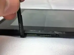
Remove the SIM card from the device to prevent damage.
-
To remove the SIM card, open the SIM card cover on the side of the device.
-
Push SIM card in and pull it out after hearing a click.
-
-
-
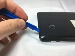
Take off the back panel.
-
Pry open the back cover carefully with a plastic opening tool.
-
Use the opening tool to disconnect the cover completely. Do not attempt to pry the back cover off with your hands.
-
-
-
Remove the charging (micro-USB) port.
-
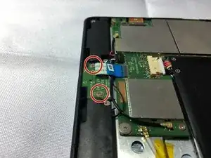
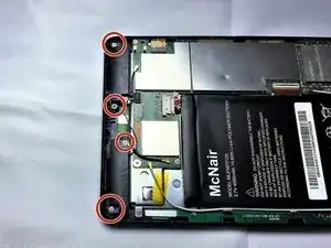
Unscrew the indicated screws using the Phillips #00 screwdriver.
-
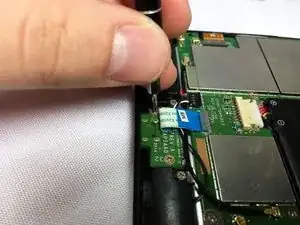
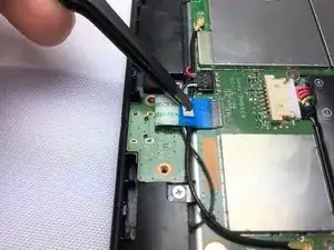
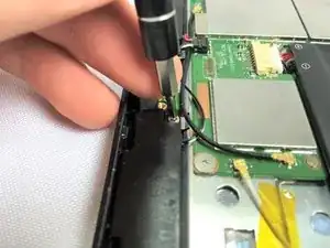
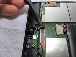
Disconnect the ribbon cable connecting the charging port board to the motherboard using tweezers.
-
Use the tweezers to grab the sides of black, plastic connector. Do not grab from the wires or try to wedge it out from the bottom.
-
-
-
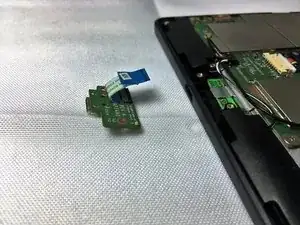
Remove the charging port board from the phone using tweezers.
-
Place the replacement charging port into the phone.
-
-
-
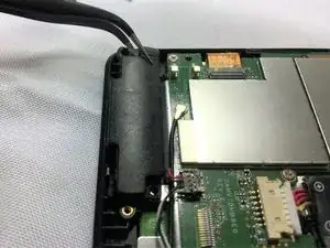
Using tweezers carefully lift the connector up to disconnect it from the motherboard.
-
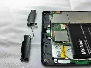
Using tweezers carefully pull the speakers up and out of device.
-
To reassemble your device, follow these instructions in reverse order.
