Einleitung
Werkzeuge
Ersatzteile
-
-
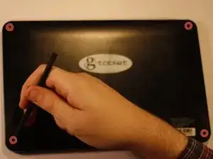
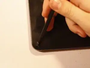
Using your spudger or metal tweezers, work the rubber screw covers out of their sockets, found on each of the four corners of the back cover.
-
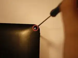
Using a PH00 screwdriver, remove the 5.8mm screws found beneath each rubber cover (4 total).
-
-
-
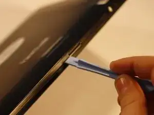
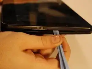
Using the flat end of your prying tool, work the back cover away from the rest of the gTabet.
-
Starting near the charging port, work in one direction around the perimeter of the device.
-
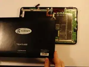
Lift off back cover to reveal the interior of the device.
-
-
-
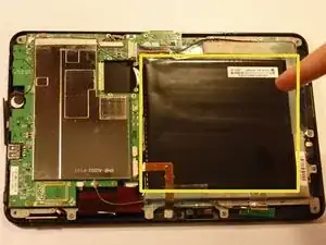
The battery is the large black square that dominates much of the device interior.
-
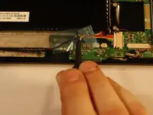
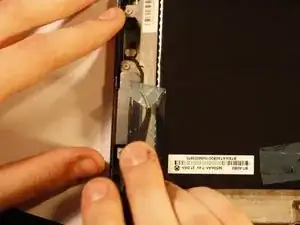
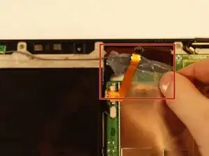
There is tape holding several wires in place. This must be removed before the battery can be removed. Peel it gently; you will want to use it later.
-
-
-
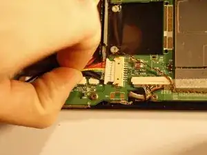
Using a PLASTIC tool of your choice, push both ends of the power cable connector, one at a time, away from its housing. This will slowly wiggle the connector out of place.
-
-
-
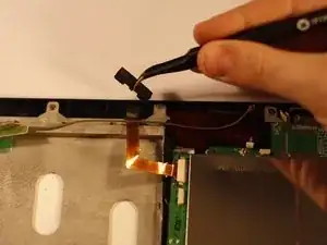
Using tweezers, remove the protective foam backing arch from the front-facing camera.
-
Pull the camera out of its housing and move it aside.
-
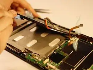
Gently lift the battery up and away from the rest of the device and set it aside.
-
-
-
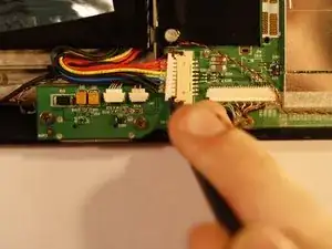
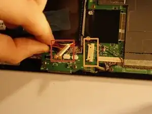
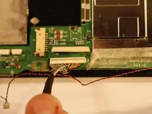
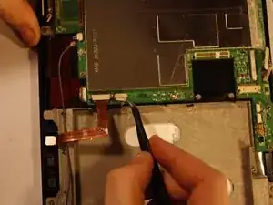
Disconnect the LCD Video cable, shown to the right of the battery power housing. Gentle application of pliers is acceptable for this extra large connector.
-
Two additional connections must be undone before moving on. One can be found to the right of the front facing camera housing on the motherboard. It is small; treat it gently.
-
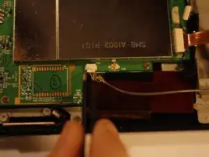
An identical connection can be found next to the antenna connection of the motherboard, diagonally across from the one you just disconnected.
-
Now all necessary wire connections have been undone and the motherboard can safely be removed.
-
-
-
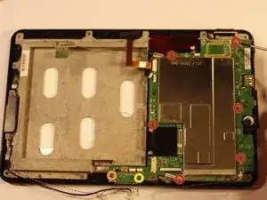
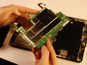
The motherboard is mounted to the chassis by 8 screws, which must be removed.
-
Gently lift the motherboard away from the remainder of the device. Set aside in an anti-static bag if you have one. If not, avoid placing it on surfaces prone to static shocks (fabric or metal for instance).
-
-
-
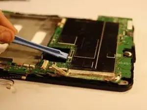
There is another circuit board affixed to the LCD chassis (back covering) that must be removed before the chassis can be unscrewed.
-
The glue holding this component on is strong; it takes patience to pry off the plastic covering without separating it from the electronics inside. Pry with a spudger in small increments. With patience, it will come undone.
-
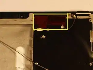
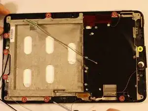
Finally, begin removing the chassis of the LCD screen by removing the 6 screws (4.5mm) found around the perimeter of the chassis with a PH00 screwdriver. The sevelth screw, circled in yellow, is stationary and must simply be loosened.
-
-
-
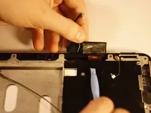
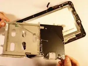
Remove the LCD Chassis. Notice the antenna and accompanying wire stay attached.
-
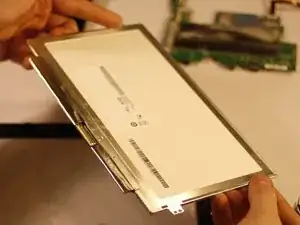
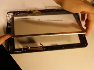
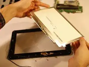
Lift the LCD screen from the "top" of the device (the long side with the front facing camera). There is a small piece of double sided tape holding it in place on the bottom; continue lifting to free it.
-
To reassemble your device, follow these instructions in reverse order.
