Einleitung

Wacom Cintiq Pro 13 is a tricky device to disassemble.

  • Main screws holding the casing to the display are hidden under rubber feet held by strong adhesive.
  • Most screws however, are common #0 Phillips type and come into two sizes, easy to distinguish between casing screws and mainboard screws.
  • Replacement components are not easily available and the easiest way to get them is to buy a broken unit and swap parts as needed.

Before you begin, there are not a lot of user serviceable parts inside - take a look on the “Internal Components” list on the main page of the device to see what can be replaced without soldering and mainboard component level servicing knowledge.

  1. aE1pXSYxJ2ytdMHJ
    aE1pXSYxJ2ytdMHJ
    JRpyNXLsnQuwrFZF
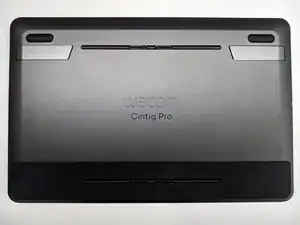
    • Place the device with the display facing the floor.

    • Make sure the surface won't scratch the display of the the tablet

  2. 2jNXSbmreAy2kMEH
    2jNXSbmreAy2kMEH
    XPKYoN5OcrhJiFZo
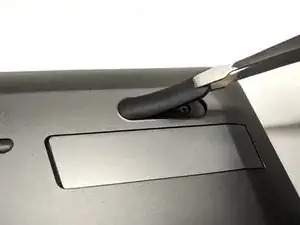
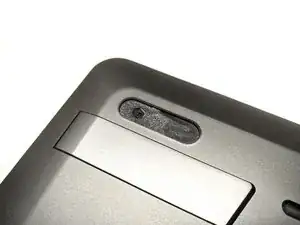
    • Remove two rubber feet on both sides of the tablet

    • Use plastic tools to lift rubber feet to avoid scratching the back cover

    • Remove two #0 Phillips screws hiding under rubber feet

  3. ECtPf3t6dyFuyHVM
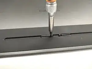
    • Remove two T5 Torx screws on the bottom of the device

    • Remove two plastic covers as they come loose

    • Removing two T5 Torx screws and shields on the top side is not required to disassemble the device

  4. e2NCxdPSuFUmPeRj
    e2NCxdPSuFUmPeRj
    ApTyEtjCxNxmveU4
    2TLebhk3WGAWDeOx
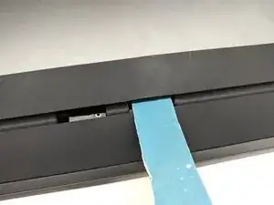
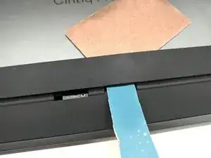
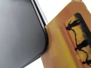
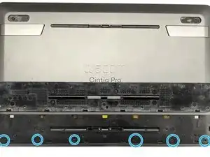
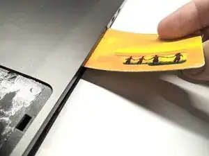
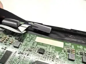
    • Heat up the bottom rubber plate near holes using heat gun or hairdryer and try to insert prying tool as adhesive softens.

    • A drip or two of isopropyl alcohol on the plastic tools can soften the adhesive even further

    • If you're using Heat Gun do not overheat the rubber plate as it may melt. You should be still able to touch the rubber plate with bare hands after heating it up.

    • Watch out for ribbon cables hiding in holes, as covers with T5 Torx screws are now removed.

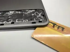
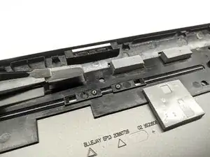
    • As the adhesive softens, try to insert flat plastic tool on the top

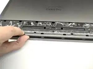
    • Heat up the rest of the rubber plate and slide plastic tool along upper side of the rubber plate

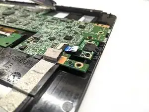
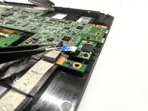
    • The bottom side of the plate has plastic clips (third image). Trying to push plastic tool too hard in lower part may result in damaging plastic clips

    • Remove the rubber plate

  5. BKNMHBwLRqZ6dvfw
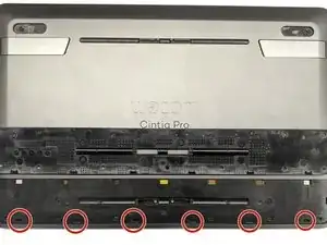
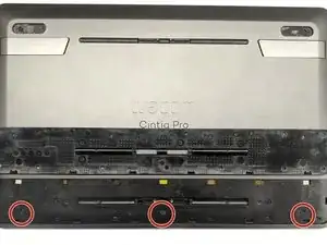
    • Remove three #0 Phillips screws

  6. 2QsLoxUPIHWyIQMZ
    2QsLoxUPIHWyIQMZ
    LIHRtsKpsniHOIXY
    4aLoGBGZ445TJWPu
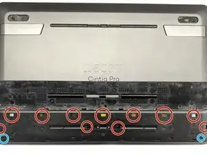
    • Unclip ONE of top left/right clips holding back plate to display frame

    • Do not push in any of red circled holes - it may break ribbon cables, display or front glass

  7. KXmbTeBVGXtwIpAR
    KXmbTeBVGXtwIpAR
    CSkmJ6eFfwbqUTle
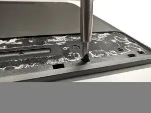
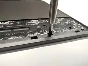
    • Push gently on the clip to allow flat plastic tool to be inserted on the corner of the device

    • Pushing too hard or pushing in holes circled red in last step may result in damage

    • Insert flat plastic tool between the rubber glass frame and the back panel

  8. WSl1EVq6WrEwOZet
    WSl1EVq6WrEwOZet
    dEBJZamcKFuLLUhe
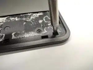
    • Unclip rest of visible clips

  9. QGOJwvUMNAbDmK1P
    QGOJwvUMNAbDmK1P
    kn4rRbEjJaGjJg44
    B1vBL5yCpFRVfdFT
    • The bottom part of the device will come loose allowing you to place finger between the case and the display assembly

    • Unclip hidden clips on left or right side and continue to opposite side. Plastic flat tool may come in handy here

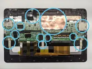
    • You can insert plastic tools up to 2 cm / 1 inch inside and not damage anything. Third image will guide you through clips and other obstacles

    • Unclip all twelve clips. Keep one hand on the display to decrease display bending and second to slowly lift the back cover.

    • There is nothing connected to the back panel - no need to worry about hidden flex/ribbon cables

    • Remove the back cover

    "There is nothing connected to the back panel - no need to worry about hidden flex/ribbon cables"

    Be cautious... 16 pro has 2 fan cables connected with the back cover!

    Jakub Pułka -

  10. 2ZqyaMZuwfM1loUU
    2ZqyaMZuwfM1loUU
    BKUMrWBMJWouGl1U
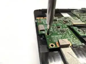
    • Remove ten #0 Phillips screws

  11. xZqeLUxIkZGXGeXO
    xZqeLUxIkZGXGeXO
    eoWRvgYT2Vv6CttL
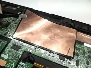
    • Remove the shielding and various tape strips holding cables

    • Pulling too fast and/or too hard may disconnect cables with the shielding or tape strips causing them to be damaged or even damage cable connectors on the mainboard

  12. sgSSgnSFttvvT5Vi
    sgSSgnSFttvvT5Vi
    RYhMo4wCJiC4FIQZ
    • Remove thermal pads

    • You can place thermal pads onto the back plate, as there are special holes for every of them

  13. 1kAqVuYqXS5fC2Fq
    1kAqVuYqXS5fC2Fq
    AVvBaFhV1QPhMNaa
    AfYGesfh6r1GnLam
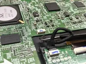
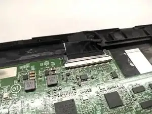
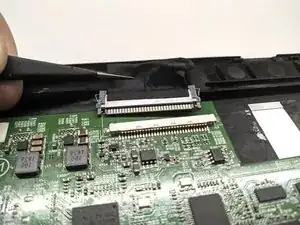
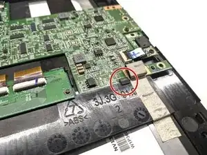
    • Release the latch of the audio jack flex cable port on the mainboard

    • Try to slide the flex cable towards the audio jack board and then lift it up

  14. HPXZdmSlBhLFC6ss
    HPXZdmSlBhLFC6ss
    vRWP2wsfDH3TEkhF
    4PmggHvjhZXxwuwB
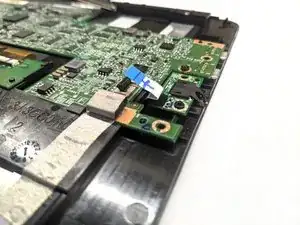
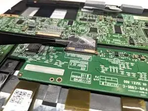
    • Release the latch of the control board flex cable

    • Try to slide the flex cable towards the mainboard and then lift it up

    • Repeat the procedure for the flex cable connector on the mainboard

    • Remove the cable

  15. U2yI5n2KnTYurOuA
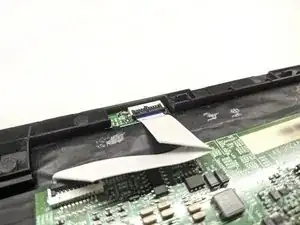
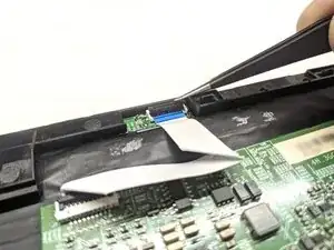
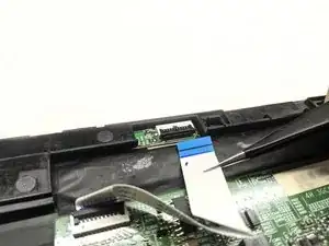
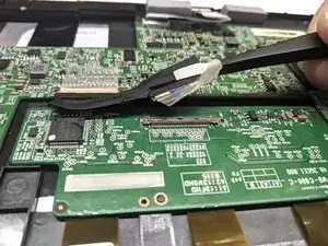
    • Remove the digitizer board cable

    • Try to hold it as near the plastic connector as possible and then pull it towards the digitizer board

    • Do not pull by the middle or opposite end of the cable

  16. LlSJplU2AU2QsTDR
    LlSJplU2AU2QsTDR
    JZGEXOkYvp2cQIpJ
    IeDuvCuen1DKKRa5
    • Remove the adhesive from the mainboard

    • Do not remove it entirely - it's a part of the cable

    • Slide the cable towards the mainboard by holding it as near the connector as possible

    • Do not pull by the middle or other end of the cable

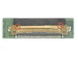
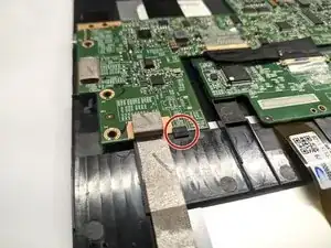
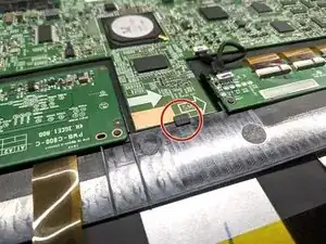
    • If cable seems hard to remove, try to push one side of the connector using a pair of tweezers by spots marked on third image

    • Do not push center part of the connector as it can be easily bent

    • Repeat the steps for another end of the cable connected to the mainboard

  17. jKmYl6TXegccMaVw
    jKmYl6TXegccMaVw
    m1ijj2FNBsUNDSyL
    KdUWMlZfnfWdZtXv
    • Remove the display connector

    • Press on the latch on left or right side of the cable

    • Slide one part of the cable just a bit

    • Repeat steps for the other side of the cable

    • Slide out the cable

    • If you wish to replace the cable, steps to disconnect the cable from the LCD display are the same as digitizer cable from last step

    • Do not pull by the cable - try holding onto the plug

  18. ydKQuRGO1DOsDKXD
    ydKQuRGO1DOsDKXD
    evaE6TWDurh6a6jg
    mGoOEIfCAYFjsoaP
    • Remove the mainboard by sliding it forward and then lift it up

    • Watch out for three clips holding the mainboard on the bottom side of the tablet

Abschluss

To reassemble your device, follow these instructions in reverse order. It is recommended to replace adhesive under rubber feet and the bottom rubber pad.

hyperhexa

Mitglied seit: 23/07/20

515 Reputation

2 Kommentare

Thanks for this guide - it’s great!! I have a Wacom Mobile Studio Pro 13, and have just managed to order a new battery - would the guide above be enough to follow to access and remove the battery? Or do you think there may be some additional steps? Im not familiar with the Cintiq pro, but assume theyre reasonably similar…

sim marriott -

Thank you for the Guide. The Cintiqe Pro 16 is of the same build and the open up part of the guide also works for that.

Differences:

Step 5: There are 7 Screws under the rubber

Step 9: The full cover has the two fans embedded into it, which are connected with 2 cables to the baseboard. You can simply unblug those to get the cover off.
Gerald Degeneve -