Einleitung
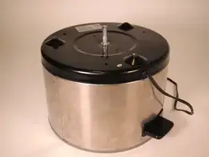
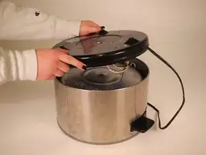
This guide will demonstrate how to disassemble the West Bend Crockery Cooker 84356. Before beginning make sure to unplug the device. While the disassembly is in process, make sure not to plug the device in at any point.
The West Bend Crockery Cooker 84356 is a fairly basic device with no digital timers or automatic warnings. Due to this simple design, it should be fairly straightforward to disassemble.
This is a relatively simple disassembly with only a few tools needed. For this disassembly you will need a pair of large needle nose pliers, metal spudger, and halberd spudger.
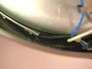
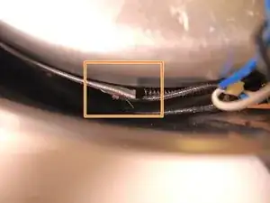
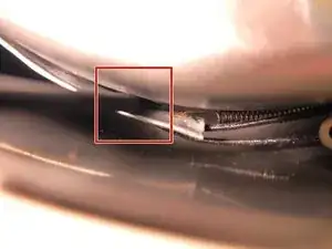
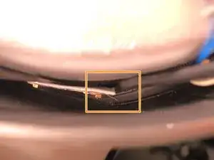
It should be noted that the most difficult steps will be Step 6 and Step 7. There is a very small gap between the side of the pot and the heating component. It will take the longest time and the most strength/force to unlatch the spring from the metal strip. Be careful in this step because the spring will snap back, so make sure not to get your face too close to the opening of the pot.
Werkzeuge
-
-
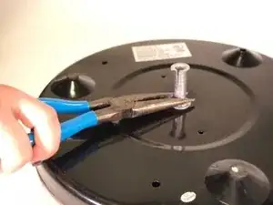
Turn the pot upside down. Use a pair of long nose pliers to crush the long rivet.
-
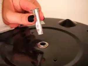
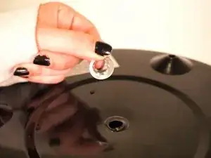
Remove the long rivet once it is crushed.
-
-
-
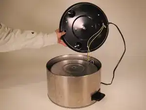
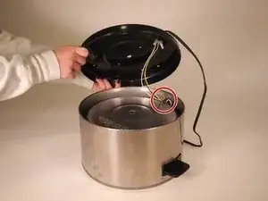
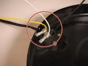
Follow the white wire that connects to the lamp inside the slow cooker. Find the yellow lamp.
-
-
-
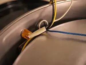
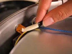
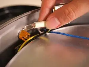
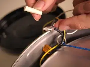
Gently pull on the wire at the bottom of the white sleeve. Remove the light from the yellow tinted case. Remove the white sleeve from wires and the light.
-
-
-
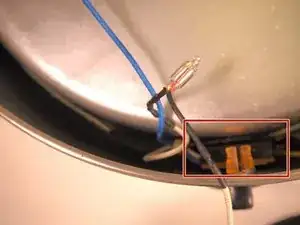
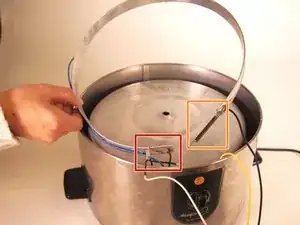
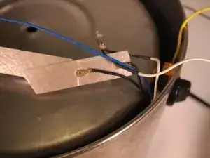
Find a black box directly underneath the light. Follow a black wire that connects to a metal strip.
-
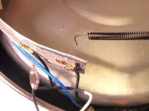
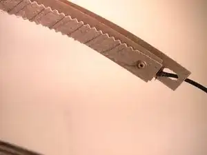
The metal strip is attached to the rest of the piece with a black spring.
-
-
-
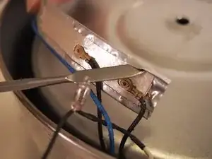
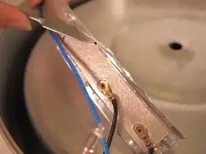
Insert the metal spudger between the metal strip and the metal pot.
-
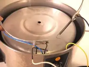
Use the black Halberd spudger to latch onto the spring, removing it from the metal strip. When the spring is disconnected the metal strip will lift up from the pot.
-
-
-
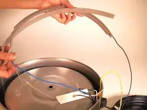
Carefully remove the metal strip from around the pot.
-
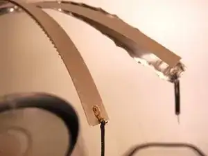
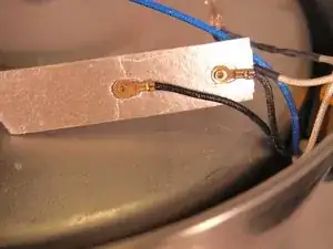
One side should be attached to two black wires and a blue wire.
-
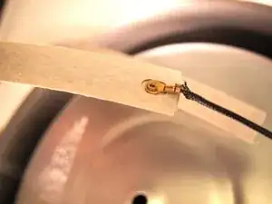
The other side of the metal strip will be attached to one black wire and the spring.
-
-
-
Using the metal spudger, go along the outside of the metal strip, propping up the metal foil and removing it from the strip.
-
-
-
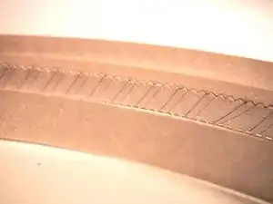
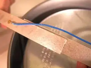
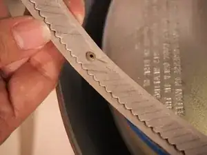
This will leave you with a long strip of metal foil that can be completely removed from the device. Once removed, there will be three strips of sheet mica, with one strip with wire wrapped around it, inside.
-
-
-
On the left side of the strip, two black wires will connect at the end from the black switch. Then a blue wire from the switch will connect a quarter of the way through the strip. The inside shows the wrapping of the wire.
-
-
-
The right side of the strip will have a black wire connected from the switch. This wire will wrap around the sides of the sheet as shown.
-
-
-
Now that the device is disassembled here is a quick explanation of how the device works.
-
Electricity flows from the 120 V AC outlet. The power source is connected to three wires, the yellow wire, black wire and white wire.
-
The yellow wire connects directly to the switch. The white wire connects to the light, and then into the switch. The black wire also connects from the power source to the switch.
-
From the switch there are two black wires and a blue wire that are leaving on the left side. On the right side there is another black wire that leaves the switch.
-
The temperature settings control which wires current will flow through during the cooking process.
-
If the Keep Warm setting is turned on the switch, current will flow through the blue wire around the strip.
-
If the LO setting is turned on the switch, current will flow through the black wires around the switch.
-
If the HI setting is turned on the switch, current will flow through both the black and blue wires.
-
To reassemble your device, follow these instructions in reverse order.
