Einleitung

To complete this guide, you will need precision accuracy and some elbow grease.

  1. c2eRkgUiGcDEfB1H
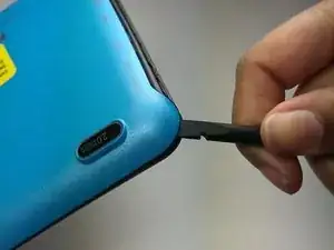
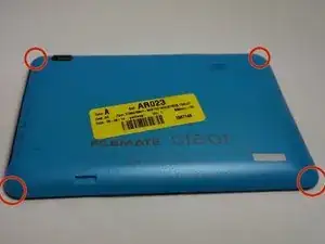
    • Locate the four corners of the backplate.

  2. KMJmXEYToObI2B5F
    KMJmXEYToObI2B5F
    16puHHDgKkmfHCaY
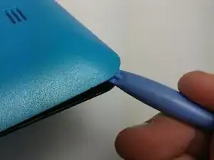
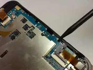
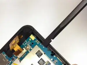
    • Pry off the backplate by inserting a spudger or plastic opening tool into each corner and popping them open.

  3. HAsNpdKFZbvGmLih
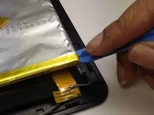
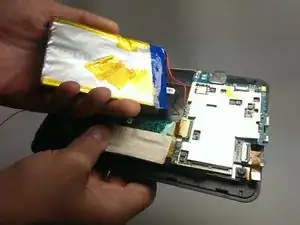
    • Un-stick the battery from the motherboard assembly with the plastic opening tool.

  4. PeqOgDoESytacauS
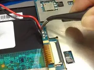
    • Desolder the battery wires from the motherboard.

    • The tweezers pictured point to the two solder joints.

  5. atBmJNwQcTXOTFia
    • Fully remove the battery from the device.

  6. BS5XeVdTbpe6VBTf
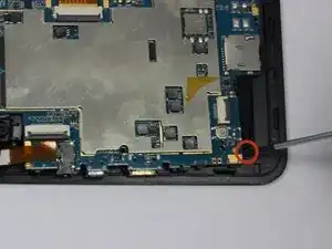
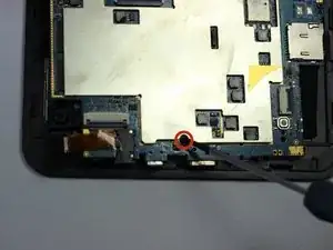
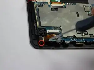
    • Locate each of the motherboard's 4 mm screws.

  7. ugCYVgyDGNgAVt1G
    ugCYVgyDGNgAVt1G
    KRvMxdTZKTAi4PmZ
    WoGLWXy1ok2VybI5
    • Remove each of the four 4 mm screws from the motherboard pictured to the left.

    • Use a Phillips #00 precision screwdriver.

  8. oGIJ5ZkshPZvjOjh
    oGIJ5ZkshPZvjOjh
    THqfUQfdlEdVKsRU
    • Use the spudger to pry the instrument array from its plastic housing.

  9. HkByYDwh6sPgULNq
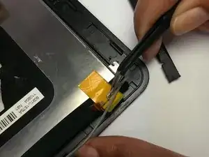
    • Slowly slide the spudger underneath the adhesive tape to un-sitck it.

    • Be careful not to harm the array of wires leading to this tape.

  10. OX5vvilasZdRe2M6
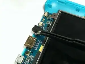
    • De-tatch the motherboard output wires from the screen using the tweezers.

  11. 5sxYSlhpBc4414wq
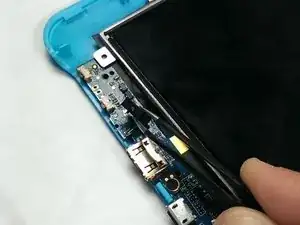
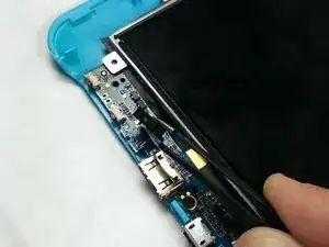
    • Remove the charging pin holster.

    • Clamp on the end of the holster with the tweezers and twist until it becomes detached.

    • Repeat for the other side.

  12. ndwg5WI5tnSmGeQN
    • Clamp onto the charging pin and twist up until it pops out of place.

Abschluss

To reassemble your device, follow these instructions in reverse order. The charging pin holster needs to be soldered back into place.
Nicholas Ferraro

Mitglied seit: 20/01/15

407 Reputation

0 Kommentare