Einleitung

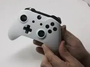
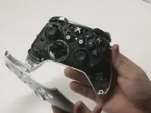
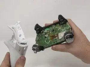
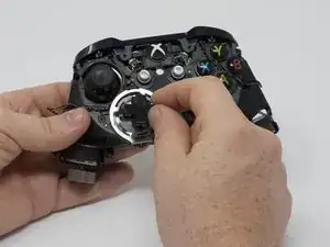
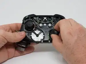
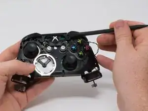
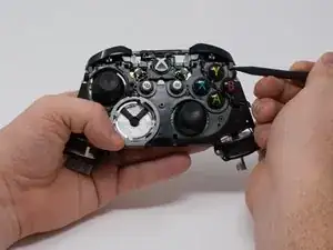
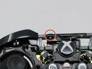
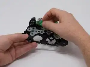
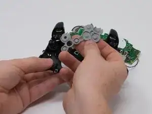
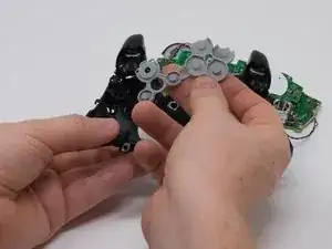
Nach und nach kann die Tasten auf der Vorderseite des Xbox Kontrollers locker oder klebrig werden. Diese Anleitung zeigt, wie sie ausgebaute und gereinigt oder getauscht werden können.

  1. CZmZL2YuctGTuPJd
    CZmZL2YuctGTuPJd
    KHyRlDiLSFSdhQPm
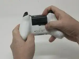
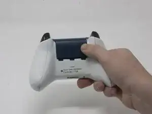
    • Schiebe die Abdeckung des Akkufachs nach oben und entferne sie.

    • Hebe die Akkus aus dem Akkufachs heraus.

  2. 1RnNtaoQqQZkbY2E
    1RnNtaoQqQZkbY2E
    wVNiZ3TUwVBoC2FL
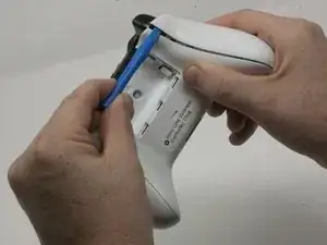
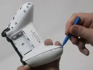
    • Setze ein Öffnungswerkzeuge aus Kunststoff in die obere Naht ein und arbeite dich dann behutsam nach unten.

    • Heble solange weiter, bis sich die seitliche Abdeckung vom Kontroller löst.

    • Wiederhole für die zweite seitliche Abdeckung.

    Only use a pry tool! The vibration motor wires are exposed and directly accessible from the side when opening. I attempted to open it with a small knife, expecting to be able to gently pry the clips open, accidentally sliced through my right motor’s wires.

    Sawyer Coe -

    Not a sharp of course.

    Kajus Slekys -

    If you have some Guitar picks laying around they work GREAT!

    Mike Beane -

  3. S6rlXDDRcqlumZ32
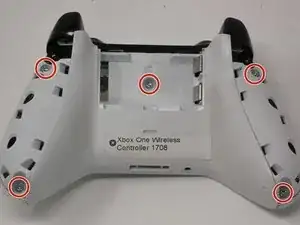
    • Ziehe den Aufkleber im Akkufachs vorsichtig ab oder öffne das Loch in der Mitte, um an die verborgene Schraube darunter heranzukommen.

    • Entferne die fünf 9 mm Torx Sicherheitsschrauben auf der Rückseite.

    Torx-8 security bits work as well.

    jahiamir -

    Torx 8 or 9 wasn’t working. I used 2.0 minus screwdriver

    richjlee -

    The 2.0 minus worked for me as well.

    metric -

    When sliding in the plastic cover during reassembly be sure it lines up with the battery compartment contacts. It can be really easy to not see it and bend the contacts. If you still encounter force during this step, depressing the triggers out of the way worked for me.

    Drew -

    Since mine is out of warranty I just broke out the security nib with a 2.0 standard bit. Then used a T8 torx.

    Tim LaCrosse -

  4. kfdJ5aNuDEUk4QSv
    kfdJ5aNuDEUk4QSv
    EaxhK2qZKFPa2bSP
    uLhJmZMFjIR1fmmF
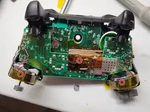
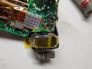
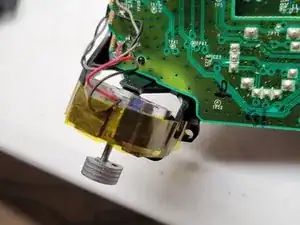
    • Befestige die Rüttelmotoren mit einem Klebeband.

    • So können die Motoren nicht herausfallen.

  5. iqgdKTgD5ghZ2AiA
    iqgdKTgD5ghZ2AiA
    k5hd4bkef3GQZcnV
    • Drehe den Kontroller so, dass die Abdeckplatte nach oben zeigt.

    • Hebe die obere Abdeckung ab.

  6. jALZRgrIkQxcoU2w
    • Drehe den Kontroller um und hebe vorsichtig die Rückseite ab.

    • Achte auf die Vibrationsmotoren, sie fallen leicht heraus und könnten die Platine beschädigen.

    Reassembly: When placing the back cover on: notice that the battery terminals need to slide inside the cover first. Then compress the triggers slightly, Then the cover will be aligned correctly. Then add the front cover and add screws so it doesn’t come undone.

    hunteil -

  7. K1gPMYdctQwIjRAw
    • Drehe das Gerät um und ziehe das Steuerkreuz vorsichtig ab.

    It needs to be made a little clearer that the thin metal retaining ring needs to be unclipped before pulling on the D-pad. A small, flatbladed screwdriver did it nicely for me.

    Paul Hough -

    As mentioned above, clarification is needed that the metal ring is intended to lay on top of the DPad - you should remove it first when disassembling, and it should be installed after the DPad to hold the DPad down when re-assembling.

    Additionally, the DPad is oriented so that the directional button without an extended tab on the end is on the bottom (down).

    sonofray -

  8. SBpFEREdAboEdgLe
    • Ziehe die Kappen von den Joysticks ab.

    Are the joystick potentiometers soldered to the mother board or just push fit, this guide doesn’t mention soldering so I’m assuming the latter?

    Can you get genuine replacement joystick potentiometers as I’ve only seen cheap eBay type ones?

    Alan -

    The actual joysticks themselves are soldered into the bottom motherboard.

    Bryan Remely -

  9. 5t5KCuZPr2OMwC1f
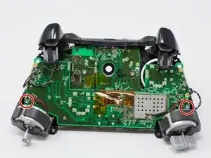
    • Wenn die Rüttelmotoren herausfallen, können sich die Kabel von der Hauptplatine ablösen. Diese Kabel müssen wieder angelötet werden.

    • Drehe das Gerät herum und entferne die beiden 70 mm Torx T6 Schrauben in der unteren rechten und linken Ecke.

    What if you don’t care about the rumble motors (always turn that feature off anyway), can I just leave them unattached?

    tracynoelle23 -

  10. pEbd1gIRs5PbH34d
    pEbd1gIRs5PbH34d
    1FZitJnwyeRqURT6
    c1vIJPoLSP2OT2FH
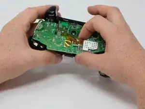
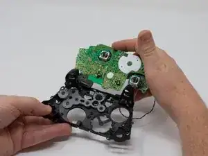
    • Halte die obere und untere Leiterplatte gut mit je einer Hand fest und ziehe sie behutsam auseinander.

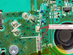
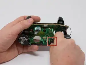
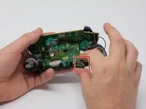
    • Die obere Leiterplatte ist immer noch mit der unteren Leiterplatte verbunden. Um sie ganz zu trennen, musst du sie ablöten.

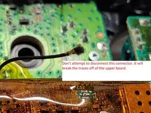
    • Warnung: versuchen nicht den goldfarbenen beschichteten Verbinder abzutrennen, er ist besonders empfindlich und geht leicht kaputt. Er verläuft zwischen den beiden Leiterplatten.

    • Anstatt den Verbinder abzutrennen, musst du das abgeschirmten Kabel an der unteren Platine ablöten. Du musst dazu ganz fein löten können.

    Soldering is not necessary for separation as on the top motherboard it uses a small connector commonly used in wireless assemblies for antennas. Simply pop it of using any prying tool or just your hand but make sure it is the side that has a gold or brassy finish and not a solder joint.

    Wyatt Faught -

    Hey Wyatt,

    Thanks for the feedback. I was on the team that authored this guide. I did not work on this specific guide so I am not familiar with this specific connector. I will follow up with iFixIt and check this issue. Thanks for the comment!

    Dylan Gross -

    Wyatt is correct that the black wire in the center can be removed from the top motherboard, but it doesn’t do any good to do so as there are two other sets of wires (grey and black twisted pairs leading to the left and right trigger) preventing you from removing the bottom motherboard entirely. These wires are visible in the pictures of this guide.

    Frank Buccella -

    I accidentally broke the part where the black wire connects to. Do I need to buy the top motherboard to fix this problem?

    drakeswifer -

    I can further confirm this as I have just pulled one apart. No soldering iron required.

    Brandon -

    What's is the name of the part for wireless on the controller

    justin edge -

    You'll see..

    Kajus Slekys -

    In my controller that black cable (the antenna like) was separated form the board is there any way to solder it again (the socket is still conected to plug)

    Dominik Gałczyński -

    I have the same problem. It popped off the board when firm pressure was applied to reconnect the wire after a repair. I'm going to attempt to apply a small bead of solder to the part that popped off, press it in place, and then heat the connector with my iron. But I am not hopeful at all. It's tight, really tight, and if it works it will be through luck alone.

    Michael Broder -

    Any luck? Theres no pad to get the solder to stick to on mine. Im assuming it is the j1 connection. Any idea what this wire is for?

    Matt Gribbin -

    Same issue here. I tried to unplug the antenna connector but the weak solder joints disconnected from the top motherboard instead. Looks like it has couple of bigger solder pads for ground/shielding(?) and one tiny pin in the middle for the actual antenna which can maybe still connect by pushing in place? Looks like a very difficult solder job as everything is so tiny.

    Kari Söderholm -

    Can someone help to find out the actual name of RF connector type?

    mntlzr -

    Hi i destroy black wire connector on top board please help me.

    Mohsen Heidary -

    It’s IPEX 4 connector, i've ordered bunch on chinese site and replaced mine. It was hard but doable.

    mntlzr -

    mntlzr : Thanks a lot for the connector type. More specifically it seems to be IPEX 4 SMD female socket on the top motherboard.

    Kari Söderholm -

    Hi yellow tape on board what

    Mohsen Heidary -

    How does the black wire reconnect? And is it necessary?

    Craig McBeth -

    I just put my controller back together (I opened it just to clean all the buttons since my son spilled some juice on it) and it seems to work wirelessly (with a PC using the dongle that came with the controller) even having broken the small black antenna cable connector off from the top motherboard. Not sure what that cable is used for or is it just an additional antenna for better connectivity. At least my controller still seems to work fine wirelessly without that cable being connected even from several meters away from the computer.

    Kari Söderholm -

    Actually nvm. Now that I tried the controller for a second time on the next day it seems to disconnect all the time so wireless is not working properly. I’ll need to try to fix the antenna cable by soldering. Probably will order a replacement connector (IPEX 4 SMD female socket) and try to solder that on.

    Kari Söderholm -

    1) TAKE HEED TO THESE WARNINGS AND BE VERY CAREFUL

    2) Instead of separating the boards completely all you need is to get enough space to pull the part out.

    *WHILE HOLDING WITH BOTH HANDS AS IF YOU WHERE PLAYING AND PUSH THE TOP BOARD FORWARD WITH YOUR THUMBS LIKE A DRAWER AND THEN LIFT UP!

    IT WILL SEPARATE JUST ENOUGH TO DO WHAT YOU NEED. *THIS TAKES CARE, FINESSE, & SOME SKILL.

    TyGuy -

  11. FhCHVTkfS5JIUAS3
    FhCHVTkfS5JIUAS3
    Slj4rrSygUsbOU66
    • Entferne die Audiobuchse von der unteren Leiterplatte.

    Can you just leave out the audio port and use the controller or u have to have a replacement to play

    Itachi Uchiha -

    Why would you *need* the audio port? If you are happy to not use then fine, this is an instructional to get it working and by extension a headset one would assume.

    Ali J -

    This piece is just placed in there - sandwiched between the two motherboards. No adhesive, no mechanical attachment, nothing.

    Andrew Sauk -

    So can it be replaced or no? I took it out it dont look fried or anything but it still dont work when reinstalled

    Frank Minelli -

  12. cNONLRgZCbNGsnNB
    cNONLRgZCbNGsnNB
    6rDVhwtVxLEGDP6K
    kwrYYSRxFHDo4xOC
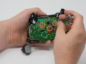
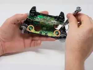
    • Entferne die drei 70 mm Torx T6 Schrauben, mit denen die untere Leiterplatte in der Mitte befestigt ist.

    • Entferne die beiden 70 mm Torx T6 Schrauben mit denen die untere Leiterplatte in der Nähe der Rüttelmotoren befestigt ist.

    • Entferne auch die 70 mm Torx T6 Schrauben von der linken Seite der unteren Leiterplatte.

  13. WRWQJIdAY3iRasrr
    • Hebe mit einem Spudger die Kunststoffsrasten von den vorderen Auflagen ab.

    • Löse die Rasten, indem du sie nach oben drückst.

    Reassembly: This hard is hard to mount. Slowly flip the controller upto view the charging port and notice it isn’t aligned yet… If you force it to outside of pcb, it’ll try to pop off. I’ve yet to figure this step out… I forced it and after full reassembly, the bumpers became REALLY stiff.

    hunteil -

    Solution: Instead remove the outside piece mentioned in image… then remove the bumpers… Check that all cavities are clear. Then make sure the sync button is inserted all the way in… Then place the left bump in the far left hole first. Then ensure the horn part slides into it’s specific slot inside, then ensure the the sync button goes in hole…then continue to right bumper side…. Then add the over cover piece above it… Start with the piece that goes over the charge port. Then the front as the above image shows… Now check your bumpers for easy clicking… If it’s still not correct, remove and try again gently as the horns may snap off and the PCB may get damaged.

    hunteil -

    Note: I believe the order is very important or the alignments on the left side may have the horn forced into one of the other close cavities and you won’t even know it. (This causes that horn to get damaged over time too. Without the horn, the bumper will drift and miss the button and bind up the trigger.)

    hunteil -

    PS: Rubber band to hold triggers down slightly helped a ton! Otherwise the trigger is over extending into the bumper assembly space.

    hunteil -

  14. QiaHv1Y56eTQ1Rrl
    QiaHv1Y56eTQ1Rrl
    TPLNYnlCbHTeWXNN
    • Löse die kleinen Haken am Ende der rechten und linken Seitentaste mit einem Spudger.

    • Nachdem du diese Haken gelöst hast, trenne vorsichtig die Vorderseite des Kontrollers von der Rückseite. Die Connect/Sync Taste (zweites Bild) wird von der vorderen Seite festgehalten und löst sich bei diesem Schritt.

    Watch for the tiny button that sticks out from the top - it’s the wireless connect/sync button.  It will fall out and is easy to lose.  During reassembly, I found it easier to put the bumper back in first, then use a tweezers to insert the button back into place.

    w.m. williams -

    Anyone know what part to look for when ordering replacements? I mean the switch itself, to solder it back on to the PCB

    Adam -

  15. 3lKUbADDACjL44bC
    • Um Schäden an den Kabeln zur Leiterplatte zu vermeiden musst du die Leiterplatte so wie ein Laptop aufklappen.

  16. NopVS6Dg4BAL1bdW
    NopVS6Dg4BAL1bdW
    FgILUkbp1HZtoWUF
    • Hebe den Abdeckstreifen aus Gummi hoch.

    • Wenn der Abdeckstreifen weg ist, kommen die Tasten leicht heraus.

Abschluss

Um dein Gerät wieder zusammenbauen, folge den Schritten in umgekehrter Reihenfolge.

Dylan Gross

Mitglied seit: 25/09/17

4590 Reputation

8 Kommentare

Thanks for the contribution for you and helped a lot of people.

NELSON ESTREMERA -

You don't need to desolder anything to remove the top motherboard!

Those black and grey wires go to the vibration motors in the triggers. Remove the covers on the triggers along with the motors, and carefully remove the wires from clips on the front of the controller. Make sure you get the black signal wire. You can now safely remove the two boards from eachother.

randomguy6527 -

I needed a guide for this because my “X” button was sticking and I ended up doing the whole thing without separating the motherboards, cleaning everything that touches the button, and it worked like a charm. Thank you very much for the guide!
Michael Winay -

Can you just take off the buttons right after removing the front faceplate?

Zanyar -

I wore out both the sticks playing COD, this helped me to make it usable enough for P2. cheers!

Nicholas Pratt III -

Just a heads up for people, there is an antenna wire that the guide leaves, takin it off the top board make your life easier and is very easy to put back on

Nolan Keilty -

Good easy to understand guide. 5 stars from me definitely

Odis Ernest -

Please remove the soldering part it is not necessary at all, it almost put me off. As for the rest good info

Heartman -