Einleitung
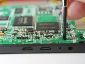
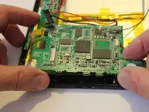
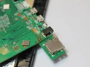
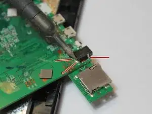
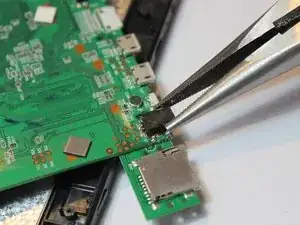
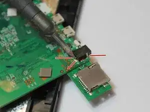
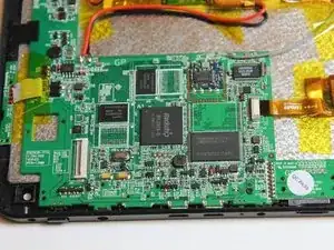
If the power connector on the Xelio P1001A-BK tablet is damaged, it can be de-soldered from the motherboard and replaced with a new part. This is a 2.5mm x .7mm power plug which should be readily available from most electronic parts stores. The repair should take about one hour for the intermediate do-it-yourselfer.
Since the motherboard will be exposed, care should be taken to prevent short circuiting the power leads from the battery or allowing static electricity to damage the motherboard. An antistatic mat should be used if available.
Be patient and go slow with this repair as several small parts will be removed and the could be easily damaged or lost. A magnetic mat or parts tray is recommended to keep small parts together.
Werkzeuge
Ersatzteile
-
-
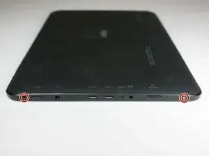
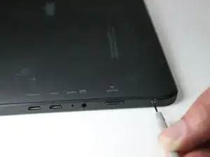
With a Phillips #0 screwdriver, remove the two 3 mm retaining screws from the side of the tablet.
-
-
-
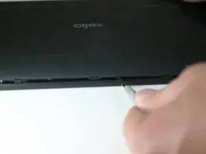
Using the plastic opening tool, disengage the securing tabs that are along the two long sides of the tablet, four on each side.
-
Slowly rotate up the side of the tablet opposite from the control buttons.
-
-
-
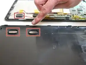
If they are, the shell half can be fully separated from the front shell half.
-
If they are still in their sockets, gently pry them loose with the plastic opening tool.
-
-
-
Remove the motherboard to screen ribbon cable
-
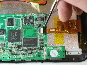
Pry the ribbon cable retaining tab loose with plastic opening tool.
-
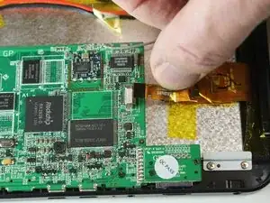
Slide the ribbon cable out from the connector.
-
-
-
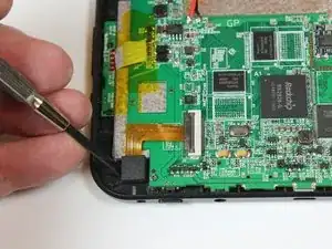
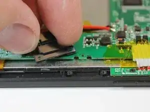
Remove the two motherboard retaining clip screws with a No. 0 Philips head screwdriver
-
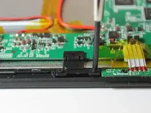
Remove the retaining clip from the board.
-
-
-
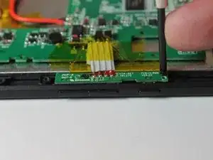
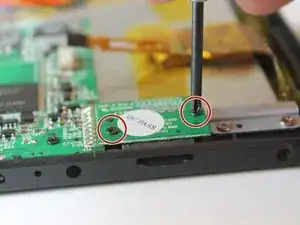
With the No. 0 Phillips head screwdriver, remove the two screw that hold the function and volume control switch assembly to the tablet.
-
-
-
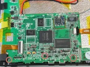
Gently lift the motherboard free from the tablet frame and turn it over to expose the opposite side. This will expose the power socket solder pins.
-
Be cautious when turning the board over as another ribbon cable, the speaker wires, battery wires, and Wi-Fi antenna wire as still connected to the motherboard.
-
-
-
Place the motherboard back into its proper position but do not reinstall the securing screws yet.
-
-
-
Plug the tablet power supply into the power socket
-
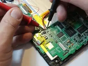
Using a volt-ohm meter, touch the meter probes to the battery wire points on the motherboard to ensure voltage is getting to the battery.
-
To reassemble your device, follow these instructions in reverse order.

