Einleitung
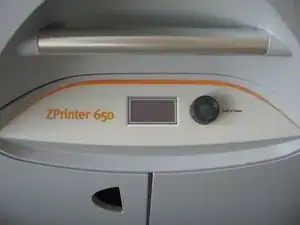
If you own a ZPrinter 650 color powder 3D printer, you may have experienced issues with the large electronics module, which is prone to failures. Unfortunately, replacement modules can be incredibly expensive, costing around $5000 USD in 2015. To make matters worse, the original producer, Z Corporation, no longer provides spare parts for older printers manufactured before 2012 since they were acquired by 3D Systems.
However, there is a solution to this problem. After conducting some research, I found that the main reason for these failures is due to a small, embedded PC mainboard that is based on the VIA C3 processor. The Taiwanese factory that produced the board seems to have used an inadequate CPU fan, which causes the CPU to burn out when it stops working. In some instances, the fan has failed after only two months.
While the CPU cannot be replaced as it is soldered to the board, it is possible to purchase a new mainboard. The replacement part has the part number ENDAT-3220M and can often be found on sites such as eBay or PC surplus stores. Keep in mind that other Z Corporation printers also use this mainboard, such as the ZPrinter 450 and ZPrinter 250, but it may depend on the production year or revision of the printer. Therefore, I recommend disassembling the printer and checking the actual mainboard type before purchasing a replacement. With these steps, you can save yourself a significant amount of money and get your 3D printer back up and running in no time.
Disclaimer
This repair should be performed only by skilled technicians only! Moreover, it includes manipulation with very sensitive electronic components, thus proper ESD precautions must be met!
Werkzeuge
Ersatzteile
-
-
Before replacing the mainboard, it is important to thoroughly troubleshoot the problem to ensure that it's the source of the issue.
-
Normally, the mainboard produces a short beep about 10 seconds after powerup. If it doesn't beep, then it's probably dead.
-
If the printer produces multiple or repeated beeps, it is a sign that the mainboard is likely functional, but there may be another component that has failed, such as a dead CMOS battery or bad memory.
-
Another indication is the front display - If all pixels remain black, it may be an indication that the mainboard is dead. If the display does not light up at all, like in the photo, it may be a sign of a different issue, such as a dead power supply for the electronics module.
-
-
-
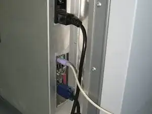
Power down the printer and disconnect all cables from the electronics module on the back.
-
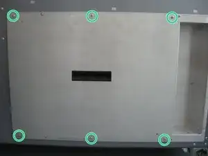
Remove the cover by unscrewing the 6 screws and setting it aside.
-
-
-
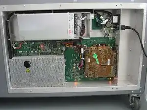
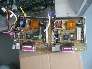
After powering up the printer, allow it to run for at least 10 minutes. Check the temperature of the board on the back side of the CPU (green arrow). If it is hot (> 50°C), this may indicate a burnt-out CPU.
-
Additionally, you can check if the original CPU fan is functional. If it does not work, this may also indicate a burnt-out CPU. Refer to Step 9 for further instructions on how to check.
-
-
-
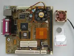
Once you have confirmed that you have a faulty mainboard and purchased a replacement, you need to prepare it before installation.
-
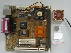
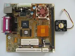
Begin by replacing the original fan as a preventative measure to avoid future issues. Use the best fluid dynamic bearing fan you can find, such as the Noctua NF-A4x10 FLX featured in the photo. Any other high quality 40x40x10 mm fan with a 12V 3-pin connector will work as well. Don't forget to connect the fan cable.
-
Next, replace the original CMOS battery (CR2032 type) as a preventative measure, as the mainboard may have been in a warehouse for eight or more years, causing the original battery to die.
-
-
-
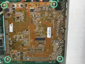
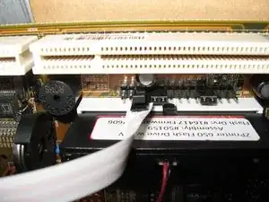
Before removing the mainboard, unplug all cables from the printer and remove the 4 screws as indicated in the photo.
-
Gently pull on the left vertical edge of the mainboard, being mindful of the resistance that you will feel as a PCI riser card disconnects (see Step 7 for more details).
-
-
-
Place a pedestal on the ground to support the original mainboard while you work on it; a cardboard box works well.
-
Review all the components that you need to move to the new mainboard:
-
DDR memory stick
-
Small Parallel ATA solid state hard drive
-
Power supply converter and connector
-
White ribbon cable for the "power button" header
-
-
-
This part is a bit tricky, because you need to connect the mainboard onto PCI riser card as you slide it in.
-
Begin by placing the mainboard connectors onto the I/O shield at an angle, as shown in the first photo.
-
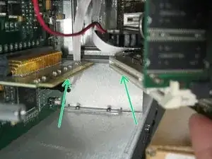
Gently push the left edge of the board and verify that the riser card is properly mating with the PCI slot, indicated by green arrows in the second photo.
-
If everything looks good, push the mainboard all the way onto the hexagonal mounting posts and secure it in place with screws
-
-
-
Before connecting the Ethernet cable, test if the new mainboard has resolved the issue that caused the fault.
-
Connect a PS/2 keyboard and a VGA monitor to the mainboard. Plug in the power cord of the printer and turn it on. The mainboard should beep and show the BIOS logo. It may stop and report corrupted CMOS settings due to the battery replacement in Step 4.
-
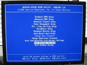
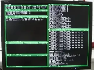
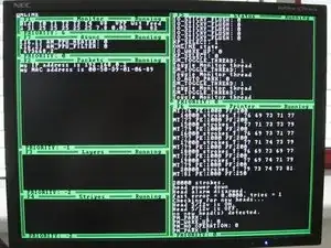
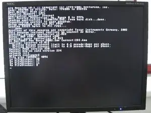
Enter the BIOS by pressing the Delete or F1 key and choose to Save settings, as shown in the second photo. This will save default CMOS settings and the mainboard will reboot itself. It should then boot into the printer firmware, with an ASCII GUI similar to the third photo. The small display at the front of the printer should also function now.
-
-
-
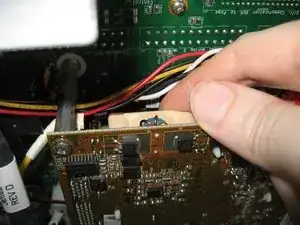
After the printer is running, confirm that the new CPU fan is mounted and plugged in correctly. You can check if it is rotating by using a small mirror or by carefully feeling it with your finger, as shown in the photo.
-
Tie up nearby cables to prevent them from moving and blocking the fan.
-
-
-
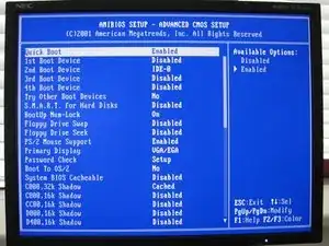
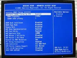
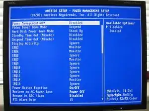
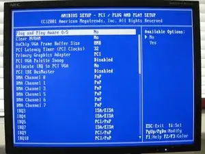
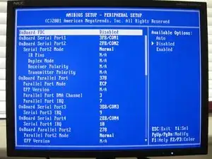
To prevent the printer firmware from freezing when you connect the Ethernet cable, you must adjust some settings in the BIOS. Specifically, you need to disable certain onboard devices to avoid IRQ conflicts. Since the firmware runs on FreeDOS, which is not a Plug and Play OS, these adjustments are necessary.
-
While I do not recall the exact settings that need to be changed, I have taken photos of a working printer that can serve as a template.
-
-
-
iFixit limits the number of photos per step to three, as such I had to split the BIOS settings into two steps. Notably, the Peripheral Setup setting is likely the most crucial.
-
-
-
Connect the Ethernet cable to the printer and observe the ASCII GUI. Normally, some values change every second and should continue to do so after you plug in the cable. If the firmware freezes, double-check the BIOS settings.
-
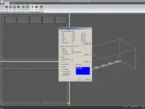
The printer should now function correctly. You should be able to connect to it immediately with ZPrint or 3DPrint software because all settings were saved on its internal HDD. Keep in mind that the new mainboard has a different MAC address, so network configuration changes may be necessary in your institution/workplace.
-
Finally, you should turn off the printer, disconnect all cables and put back cover on the electronics module. That completes the repair.
35 Kommentare
Please send me an image of the hd to aylward Edward at Gmail. Thanks
Check your mail if it arrived, our mailserver antivirus is a bit overzealous when it comes to "non-standard” attachments.
Everyone! Please don’t provide any help or information to Edward Aylward! He is from Noble 3D Printers company which defrauded my employer - we ordered binders for 1000 USD and they never delivered them. And we weren’t the only ones who they cheated:
Thank you for your guide. I have a used 450 and its mother board is/was bad. Someone replaced it with a different one and I am struggling with the board, still. The fan was dead on the NEW board! So I am betting its dead too. What a load of you know what for a $25,000 machine when it was new. Regards. Cismontguy Free Union VA. USA
A different board? You mean different part number than ENDAT-3220M? Please post its type or photos.
