Einleitung
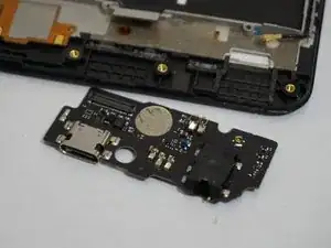
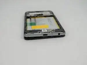
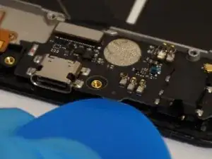
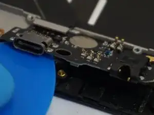
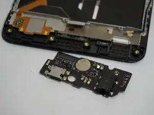
This car contains the charging port, headphone jack, and rear speaker.
The easiest way to replace any of the components on this board is to simply replace the entire board. Otherwise, you would have to desolder the faulty component and solder in a new one.
This replacement can be done without removing the battery, but due to the nature of the parts being replaced, it is highly recommended that the battery is removed before attempting this replacement.
Werkzeuge
Ersatzteile
-
-
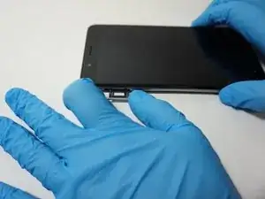
Turn the device on it side with the buttons away from you.
-
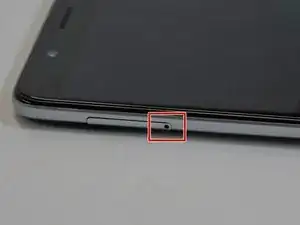
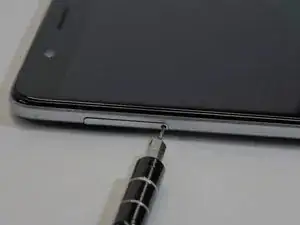
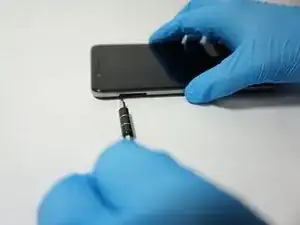
Using the SIM Card Eject Tool, insert the narrow end into the ejection hole.
-
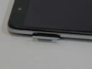
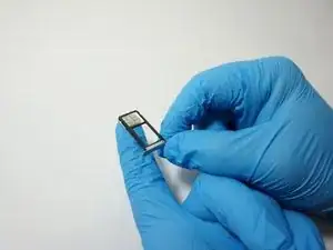
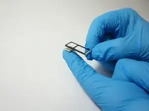
Press firmly into the hole until the SIM card tray pops out far enough to grab with your fingers.
-
-
-
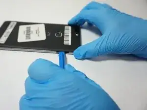
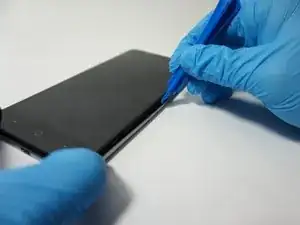
Insert a plastic opening tool into the space where the SIM card tray used to be.
-
Gently pry the back away form the phone frame until you hear and audible click of the back separating.
-
-
-
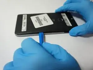
Insert the plastic opening tool into the space you created between the phone back and frame.
-
Slide the plastic opening tool along the outside of the phone, underneath the back, to separate the rest of the clips holding the back onto the frame.
-
-
-
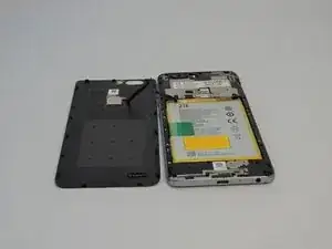
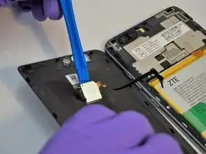
Rotate the back over to the side, being careful not to damage the fingerprint sensor ribbon cable.
-
Use a plastic opening tool to separate the fingerprint sensor from the back of the phone.
-
Set the phone back aside.
-
-
-
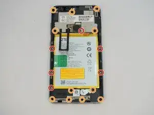
Remove the 6 silver 2.9mm screws from the back of the phone with a JIS #000 bit.
-
Remove the 11 black 3.5mm screws with the same JIS #000 bit.
-
-
-
Turn the phone over, with the screen up.
-
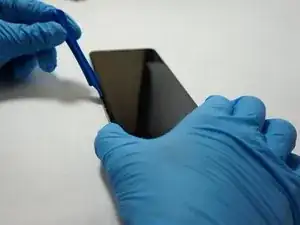
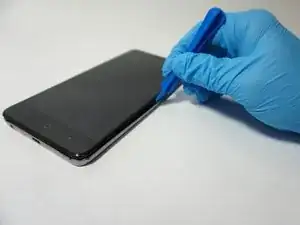
Insert the opening tool between the screen and the silver trim that surrounds it.
-
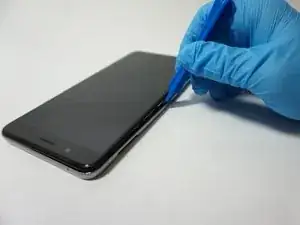
Run the plastic opening tool around the circumference of the phone to separate the clips of that hold the trim to the frame.
-
-
-
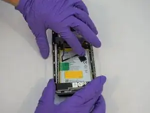
Turn the phone back over, with the screen down.
-
Lift the trim piece off of the phone and set aside.
-
-
-
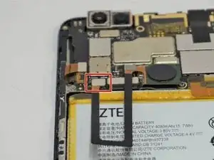
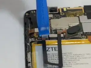
Using a plastic opening tool, separate the fingerprint ribbon connector from the motherboard.
-
-
-
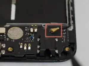
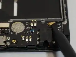
Use a spudger to pry up the the antenna connector on the top right of the charging port card.
-
-
-
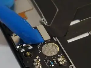
Use a plastic opening tool to pry up and remove the primary connector for the card, located on the top left of the card.
-
-
-
Use a plastic opening tool, spudger, or opening pick to separate the bottom edge of the card away from the phone.
-
Lift the bottom edge of the card high enough that you can grab it with your fingers, and simply remove it from the phone.
-
To reassemble your device, follow these instructions in reverse order.
3 Kommentare
Thanks! $7 part on ebay & this guide saved me from having to buy a new phone!!!
Is there anything special about reassembly one should be aware of? I have read that side buttons are an issue. Tips for reassembly, or what to watch closely would be handy. Thanks!
At the start of this procedure it stated to remove the battery. I never saw the battery being removed, or the power cable from the battery being disconnected from the board to isolate the power from the phone. Is this step necessary to replacing the charging port card. I know that the battery can be a bear removing it from the phone.
