Einleitung

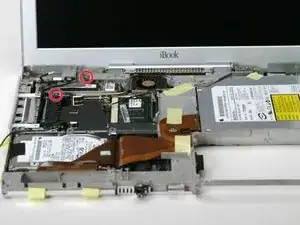
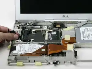
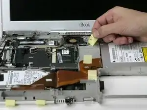
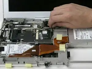
Replace worn-out inverter and AirPort cables in your display.

  1. F2vTAmGwLVVErr4j
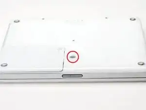
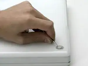
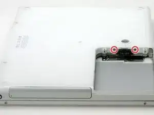
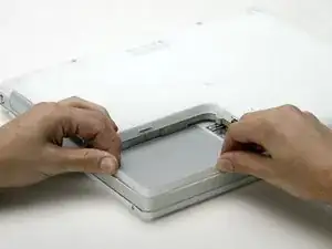
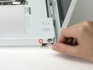
    • Use a coin to rotate the battery locking screw 90 degrees clockwise.

    • Lift the battery out of the computer.

  2. yuZdu3VoStLGYcoL
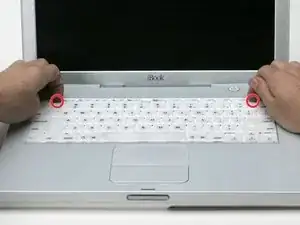
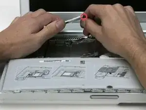
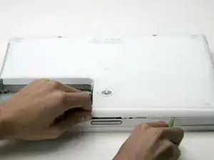
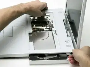
    • Pull the keyboard release tabs (highlighted in red) toward you and lift up on the keyboard until it pops free.

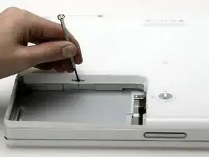
    • If the keyboard does not come free, use a small flathead screwdriver to turn the keyboard locking screw 180 degrees in either direction and try again.

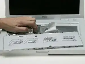
    • Flip the keyboard over, away from the screen, and rest it face-down on the trackpad area.

  3. k3QqN3kR4IW6HPjF
    • If your computer does not have an AirPort card installed, skip to the RAM shield removal step.

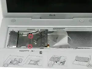
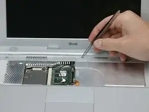
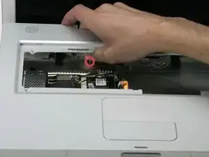
    • Push the wire clasp toward the AirPort card and pull it up to free it from the RAM shield.

  4. 6CYvr141CkpJpqel
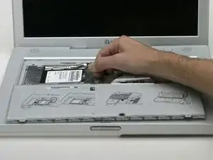
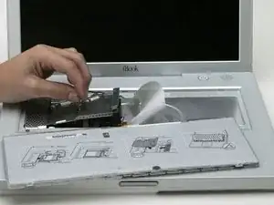
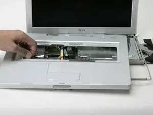
    • Grasp the clear plastic tab on the AirPort card and pull toward the right.

  5. IUdZvoTeVWaySTqC
    • Hold the AirPort card in one hand and use your other hand to remove the antenna cable.

  6. iR6wflpQB1aeDtFO
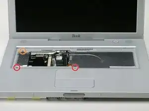
    • Remove the two Phillips screws that secure the RAM shield.

  7. tUIBmG2TxO4SHFuI
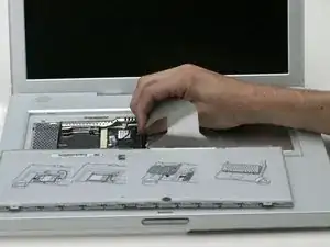
    • Grasp the metal bracket on top of the RAM shield and pull upward to remove the shield.

  8. mIZ5PbJtQ46t2556
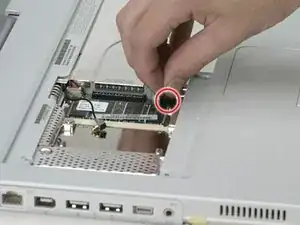
    • Pull the keyboard cable up from the logic board, holding the cable as close to the connector as possible.

  9. KRthHcTiqrtyBSog
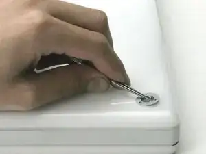
    • Use a pin to remove the three rubber feet from the lower case.

  10. TYHcZJpSmtJYjM2n
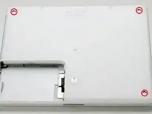
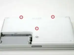
    • Remove the three newly-revealed Phillips screws.

  11. 6eQfZfA1CfM4YoFQ
    • Use a spudger or small flathead screwdriver to pry up the three metal rings that housed the rubber bumpers.

  12. aSIwY53cWQcVhxSX
    • Remove the three hex screws using a T8 Torx screwdriver.

    • The screw in the center is shorter than the other two.

  13. K2wxyhjkdXCv2FYj
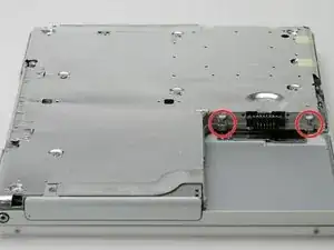
    • Remove the two Phillips screws on either side of the battery contacts.

  14. mAYq3iHXNSvKNJKn
    • Breathe deeply. Trying times are ahead, but we promise the lower case does come off.

    • Push the thin rims of the lower case surrounding the battery compartment in, bending them past the tabs, and then lift up to free that corner of the lower case.

  15. lcBWCSXS3Ye2rG24
    • There is a slot on the wall of the battery compartment that locks the lower case in place.

    • Use a small flathead screwdriver to pry out the slot's lower rim and pull up on the lower case to free the slot from the tabs holding it.

  16. lJYjvhM6FQkQJyQJ
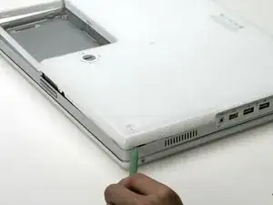
    • Run a spudger along the seam between the lower case and upper case on the front of the computer to free the tabs locking the lower case.

    • Pull up on the lower case and continue to use the spudger as necessary until you hear three distinct clicks.

  17. Y3yJqvTDpWMSgJPn
    • Continue to run the spudger around the front, right corner.

    • There are two tabs on the port side of the computer, one near the front corner and one near the sound out port.

  18. yOSsFQfNcWZBuYSp
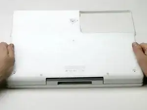
    • Once the front and sides of the lower case are free, turn the computer so that the back is facing you.

    • Pull the lower case up and toward you until the back tabs pop free.

    • It may be helpful to jiggle the case up and down.

  19. CsFpGLBpGFb3mxoV
    • Remove the small greasy springs with white plastic caps from either side of the battery contacts.

  20. VfiqSUnRr4dGeDTR
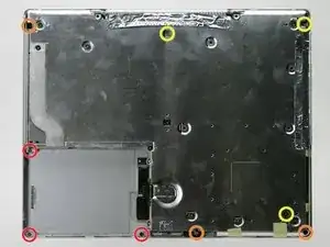
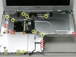
    • All of the screws in the following step have small heads - the screws with larger heads hold the bottom shield on.

    • Remove the following 9 screws on the bottom of the computer:

    • Three 3 mm Phillips around the battery compartment.

    • Three 5 mm Phillips on the left and bottom edges.

    • Three 14.5 mm Phillips on the top and right edges (you may have to peel back the foil tape to reveal the screw near the security lock slot).

  21. 6CLXTGOBhKZpDPXV
    • Turn over the computer and open it.

    • Pry up the magnet covering a Phillips screw near the middle of the computer.

    • You may need to peel back the serial number sticker to access the magnet.

    Mine didn't have a screw under the magnet.

    TekMac -

    Zitat von TekMac:

    Mine didn't have a screw under the magnet.

    I don't mean that a screw was missing, I'm saying that there is no screw or screw hole installed on my 14" in that location. The other steps were dead-on though.

    TekMac -

    No magnet, screw or screw hole on my upper case either.

    randy3833 -

    Not all G3 Dual USB iBooks have a screw underneath the magnet, so the magnet need not be removed in these cases and will not hinder the removal of the top.

    Brett Fox -

    Some iBooks like the 16 VRAM model have the magnet but there is no screw behind it.

    Alex -

    Check to see if your model has a screw under the magnet first. If you can lift up the area around the magnet there is no screw to deal with.

    James Scanlan -

  22. cqnoLLwxAXaME1aU
    • Remove the following 3 screws on the edges of the keyboard area:

    • Two 6 mm Phillips underneath the keyboard area.

    • One 9 mm Phillips above the keyboard area.

    • On some models, there may also be a screw under the magnet you just removed. If so, remove the screw at this point.

    There is a forth screw underneath the magnet: top center of keyboard area.

    tkn77 -

  23. cPDWoEqYTQYEXgOt
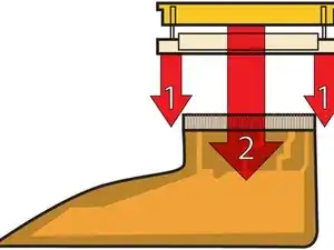
    • This is a diagram of the ribbon clamp connectors you will disconnect in the next step.

    • With your fingernails, grasp the locking bar on either side and pull up a small amount (about 1/16" or 2 mm).

    • After disengaging the locking bar, slide the cable out of the connector.

  24. kJrhDZiPODkIqVKK
    • Loosen the trackpad connector by pulling the top piece up slightly, freeing the trackpad ribbon.

    • Slide the orange trackpad ribbon out of the connector.

  25. YQm6dAIsdVYZyJFE
    • Use a straightened paperclip to open the optical drive tray, and pull it out about halfway.

  26. CEKA3gWqsHRut1Oe
    • Don't lift the upper case off the computer yet as there are still two cables left to disconnect.

    • Lift the upper case from the left side and use your other hand to pull out the right side in order to clear the power receptacle.

  27. o3jKGnVOV1YqDEGe
    • The connectors at the ends of the cables are attached very firmly to the sockets on the logic board. Pulling directly on the cable will either separate the cable from its connector or the socket from the logic board.

    • Lift the upper case enough to disconnect the blue and white power cable from the logic board.

    • Using your fingernails or a dental pick, carefully pry the connector from its socket.

    • Make sure you are pulling only on the connector and not on the socket.

    hello...while i was at step 27 i pulled the connector too much and i broken the socket from the logic board!! I used a glue to put it back but now doesen't turn on the computer...any idea??? :)

    Fabrizio -

  28. bHgIH2D6aQRTfOLf
    • Lift the upper case off completely and disconnect the red and black speaker cable from the logic board.

    • Make sure you are pulling only on the connector and not on the socket.

  29. V6MSJnUAPLX5vRDu
    • Remove the following 16 screws:

    • Five 3 mm Phillips (these have smaller heads than the others).

    • Three 5 mm Phillips.

    • Eight 6 mm Phillips.

    • If you have already removed the yellow tape, skip this step.

    • Peel back three strips of yellow tape in the bottom, left corner.

    • Peel back one strip of foil tape near the audio-out port, one near where the trackpad connects to the logic board, and one near where the screen latch used to be.

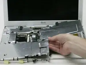
  30. 3uL53kRKtMeFFsIb
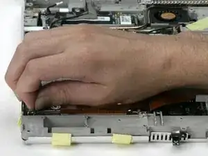
    • Lift the top shield up from the right side, minding the upper left corner, which may catch on the metal framework.

  31. JacmvQoomUPLGWgC
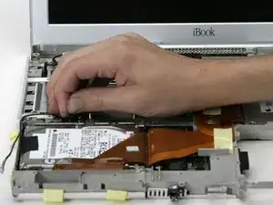
    • If you have already removed the hard drive, ignore its presence in the following steps. The hard drive does not affect the display removal.

    • Disconnect the microphone cable from the front, left corner of the logic board.

    • Peel back the black tape and free the microphone cable from the hard drive.

  32. f4BbqOcRrHTkC6PA
    • Use the black plastic handle to disconnect the display data cable from the logic board.

  33. GfKQwM1YsaSoPhs1
    • If you have already removed the modem, you will only need to remove one of these screws.

    • Remove the two Phillips screws securing the display data cable to the metal framework.

  34. 5StmykdXCkIlqmMr
    • Deroute the display data and microphone cables, removing tape as necessary.

  35. LdBGQIcqTGeMLBBg
    • Peel back the yellow tape securing the inverter cable to the metal framework.

  36. esTEFNDKGBB4PEIm
    • Disconnect the inverter cable from the logic board.

    • Carefully deroute the inverter cable from beneath the optical drive.

  37. u4HHwARlJZePKB4V
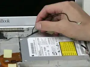
    • Deroute the AirPort antenna cable from beneath the optical drive.

  38. LLTIeHx1wW5YSs6E
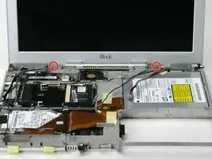
    • Support the display with your free hand removing the following screws.

    • Remove the single Phillips screw on the outer edge of either hinge (two screws total).

    • Tilt the display back to get over two small nubbins, and then slide it directly from the case and away.

  39. 6qYVuGhAAABauPOJ
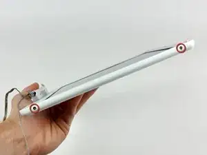
    • Use a 1.5 mm hex screwdriver to remove the two hex screws on either side of the display (four screws total).

    • If you don't have a 1.5 mm hex driver, you can probably get these screws out with a T6 Torx screwdriver. However, if you use a T6 Torx driver you'll be more likely to strip the screws.

  40. HNyZEosXt6kdG2ar
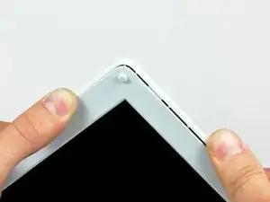
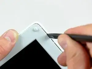
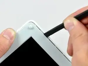
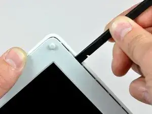
    • Use your thumbs to slightly separate the rear bezel from the front bezel.

    • It is helpful to hold the opposing corner of the display stationary to aid in flexing the rear bezel away from the display.

  41. FDXLYOLfxJJdKmQS
    FDXLYOLfxJJdKmQS
    PIG2GNTRa6yJF4qS
    FtY5eZamVfGRod3I
    • Insert the flat end of a spudger into the gap between the front and rear bezels.

    • Rotate your spudger until it is parallel to the front face of the display.

    • Run the spudger around the perimeter of the display to separate the rear bezel from its retaining clips.

  42. diGXsCWPKxZJHNxr
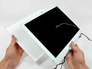
    • Lift the rear bezel off the display.

  43. Wethul6AVyi5ObGR
    Wethul6AVyi5ObGR
    uPxZKIEoqOMY5GNI
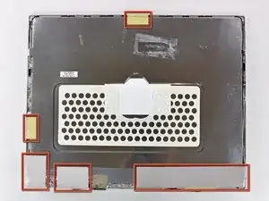
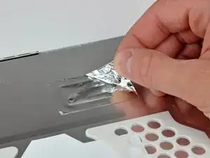
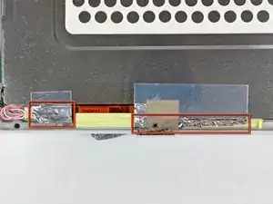
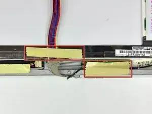
    • Remove the pieces of readily removable tape from around the perimeter of the display.

    • Carefully remove the aluminum tape covering the display data cable connection.

  44. RD1tb6sR31wKXFUZ
    RD1tb6sR31wKXFUZ
    RFSfm1QtnIoasp6i
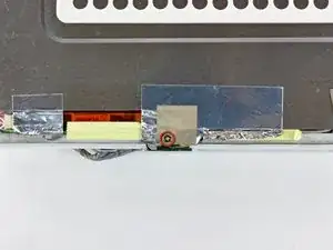
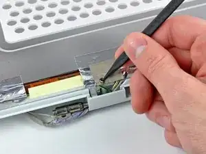
    • Remove the single screw inserted through the piece of EMI tape near the bottom edge of the display.

    • Use the tip of a spudger to remove the small washer under the screw you just removed.

  45. DnCKEjjkcIBHATfH
    • Peel the aluminum/EMI tape off the cast aluminum frame of the clutch hinges.

    • It is not necessary to peel the tape off the thin steel LCD cover.

  46. 1lfV1qWtCk2E2Qnm
    1lfV1qWtCk2E2Qnm
    IYAQ6s6Ysx1hpXh2
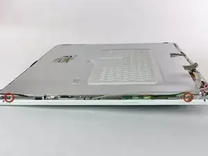
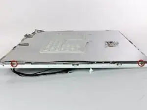
    • Remove the two Phillips screws securing each side of the LCD to the clutch hinge frame (four screws total).

  47. BDTWI3nvkn2r2XFD
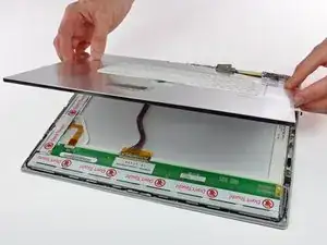
    • Lift the thin steel LCD cover off the LCD.

  48. KDTCrMp2XJGDB2Q2
    • Remove the second of the two Phillips screws securing the clutch cover to the cast aluminum frame of the clutch hinges.

  49. 16NXXyX4FCNGCoe1
    16NXXyX4FCNGCoe1
    JhkR5UMSXI2DlLD1
    PG4dVuFiO1dMT1Bd
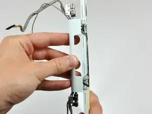
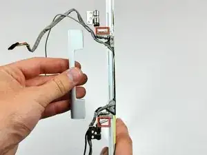
    • Pull the clutch cover away from the front of the display.

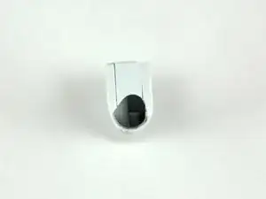
    • Keep track of the two covers that close the ends of the clutch cover. The third picture shows their correct orientation on the clutch cover.

  50. hXomfOKeTchLfiQe
    • Remove the pieces of tape covering the display data and microphone cables near the bottom edge of the display.

  51. Xcj3UVLbuXgi561q
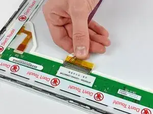
    • Disconnect the display data cable by pulling its connector away from the socket on the LCD.

    • Pull the connector parallel to the face of the LCD.

    • Remove the display data cable from the display.

  52. LCOhLBTZMLDMLofF
    LCOhLBTZMLDMLofF
    BniMcki6PN1BFboL
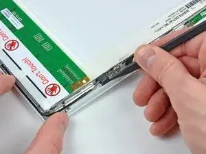
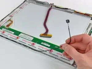
    • Use the tip of a spudger to lift the microphone out of the front bezel.

    • De-route the microphone cable from around the top and side of the display.

  53. MFRumJoCfx3xXIfc
    • Remove the display data cable from the display.

  54. EHC4KXeYmMK1PHKv
    EHC4KXeYmMK1PHKv
    PPcEKap245CXWGxd
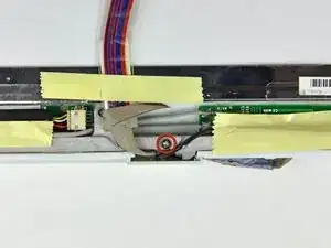
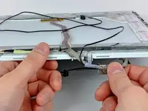
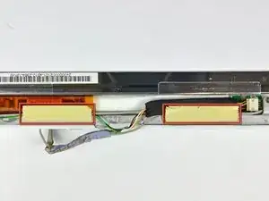
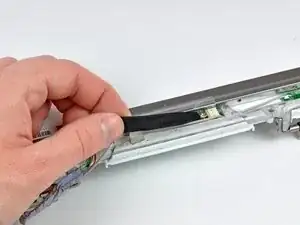
    • Remove the two pieces of tape covering the inverter/AirPort cables along the lower edge of the display.

    • Carefully peel the inverter cable ground strap off the cast aluminum frame of the clutch hinges.

  55. u23Am6yhCTZSIstb
    u23Am6yhCTZSIstb
    Oi1Dqvlf2311wNGa
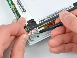
    • Disconnect the backlight cable from the inverter.

    • It is helpful to use a spudger to push the backlight connector away from its socket while you lightly pull its cables away from the inverter.

  56. BTQX6PEJu11guJJD
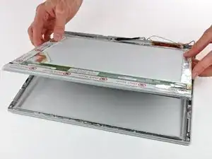
    • Lift the LCD out of the display assembly.

    • It may be helpful to press the latch release button and open your display slightly to push the LCD out of the display assembly.

  57. v5mHpNVsitDjaFpV
    • Remove the single Phillips screw securing the reed switch board to the front bezel.

    • Carefully lift the reed switch board off the metal frame of the clutch hinges.

  58. MAUWDGP3wgRpgn3j
    MAUWDGP3wgRpgn3j
    2GqF4qpKVAGsjgq5
    • Remove the two Phillips screws securing the right AirPort antenna to the clutch hinge frame.

    • Carefully lift the right AirPort antenna off the clutch hinge frame.

  59. bvvNjweIbRxLYAKG
    bvvNjweIbRxLYAKG
    AJvVN2Mf6yN2lXmt
    • Remove the two Phillips screws securing the left AirPort antenna to the clutch hinge frame.

    • Carefully lift the left AirPort antenna off the clutch hinge frame.

  60. KtEsZTvhlThdsErk
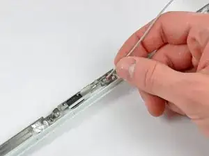
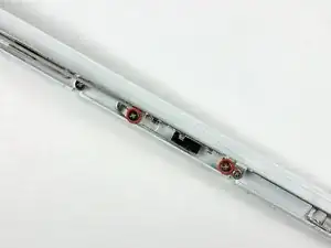
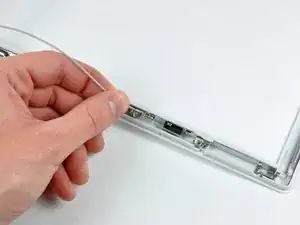
    • Use the flat end of a spudger to remove the antenna board from the front bezel.

    • The antenna board is very thin and delicate.

  61. EITwQjlAaCj2kFcT
    EITwQjlAaCj2kFcT
    ZsMXcVUTXYd5INT2
    • Remove the single Phillips screw securing the front bezel to the middle of the cast aluminum clutch hinge frame.

    • Carefully bend the front display bezel away from the clutch hinges as you slide the two AirPort antennas out from under the clutch hinge frame.

  62. UigyJMXLv2qM4Iwt
    UigyJMXLv2qM4Iwt
    OkWVCl6EcRv4Cftv
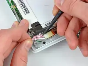
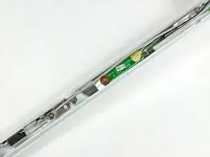
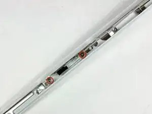
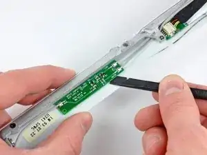
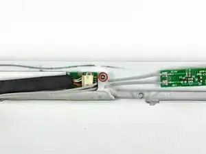
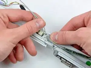
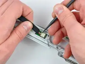
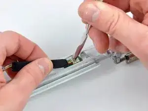
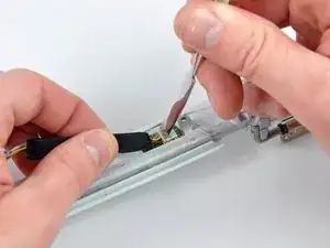
    • While pulling the inverter cable away from its socket on the inverter board, use the tip of a spudger to push the connector out of its socket.

    • If the connector won't budge from its socket, insert a metal spudger or similar tool into the gap between the connector and its socket and twist to separate the two pieces.

Abschluss

To reassemble your device, follow these instructions in reverse order.
Andrew Bookholt

578335 Reputation

0 Kommentare