Einleitung
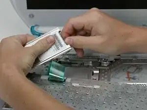
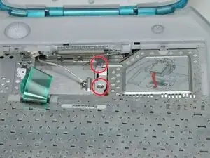
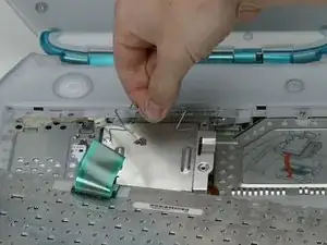
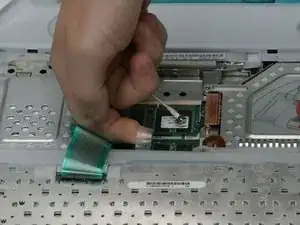
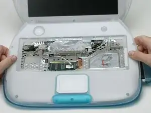
56k internal modem, standard on all models.
Werkzeuge
Ersatzteile
-
-
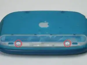
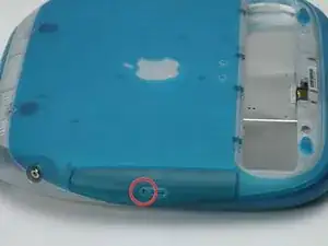
Use a coin to turn both battery locking screws 90 degrees to the left.
-
Remove the battery cover.
-
Remove the battery from the computer by pulling up on the plastic tab.
-
-
-
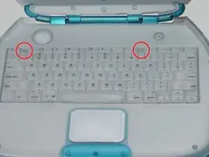
Pull the keyboard release tabs toward you and lift up on the keyboard until it pops free. Note that the keyboard ribbon is still attached to the logic board, so you cannot completely remove the keyboard yet.
-
If the keyboard does not come free, use a small flathead screwdriver to turn the keyboard locking screw (between F4 and F5 key) 180 degrees in either direction and try again.
-
Rotate the keyboard away from the screen and rest it face-down on the trackpad area.
-
-
-
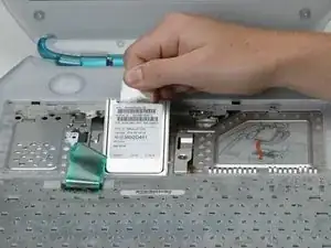
Grasp the wire metal bracket on top of the RAM shield and pull upward to remove the shield.
-
-
-
Turn the computer over so that the bottom is facing up.
-
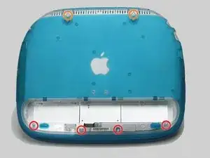
Remove the following Torx screws:
-
Four short T8 Torx near the battery compartment.
-
Two long T8 Torx near the hinges.
-
-
-
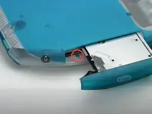
Pull the CD-ROM drive tray partly out.
-
Remove the silver Phillips screw from the plastic casing.
-
-
-
1) With your fingernails, grasp the locking bar on either side and pull up a small amount (about 1/16" or 2 mm).
-
2) After disengaging the locking bar, slide the cable out of the connector.
-
-
-
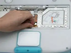
Loosen the trackpad clamp by pulling the top piece up slightly, freeing the trackpad ribbon.
-
Slide the orange trackpad ribbon out of the clamp.
-
-
-
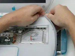
Push out the rim of the lower case and pull up on the upper case, grasping it just to the left of the optical drive.
-
Repeat the above step on the upper left corner of the upper case, grasping the bottom left corner of the upper case.
-
-
-
Grasp the upper case on either side of the keyboard space and rotate up and away from the screen.
-
-
-
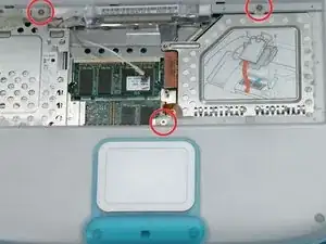
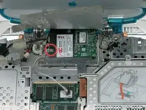
Remove the following Phillips screws:
-
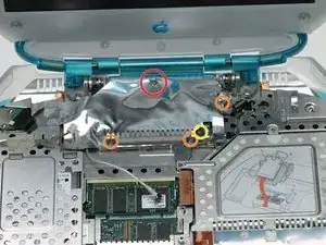
Remove the longer Phillips screw from the middle-rear of the modem shield.
-
Remove the three identical Phillips screws, two on either side of the EMI fingers, and the remaining one on the right side of the modem shield.
-
Remove the larger Phillips screw that secures the EMI fingers to the modem board.
-
Remove the EMI fingers.
-
-
-
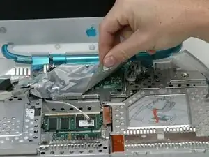
Peel the modem shield away from the metal framework below, working from the right front and moving to the left.
-
-
-
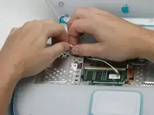
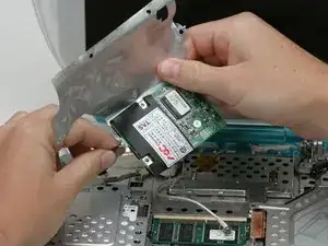
Remove the Phillips screw from the left side of the modem.
-
Pry up the right side of the modem.
-
To reassemble your device, follow these instructions in reverse order.
Ein Kommentar
is there a way to upgrade the modem so it works with modern internet feeds?
