Einleitung

Replace the display inverter with the display assembly still attached to your computer.

  1. JOMi1v5lvH4bM2Up
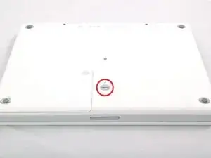
    • Use a coin to rotate the battery locking screw 90 degrees clockwise.

  2. sDUEOFFdDYPl4JYA
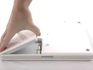
    • Lift the battery out of the computer.

  3. IWIKoGTyT42RUN4X
    IWIKoGTyT42RUN4X
    LOWBZcdvfaAFeOtn
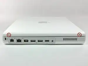
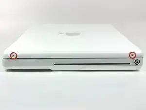
    • Use a 1.5 mm hex screwdriver to remove the two hex screws on either side of the display (four screws total).

    • If you don't have a 1.5 mm hex driver, you can probably get these screws out with a T6 Torx screwdriver. However, if you use a T6 Torx driver you'll be more likely to strip the screws.

  4. xSqrnPpT15lptQsv
    xSqrnPpT15lptQsv
    htdXBthtyHIBErbM
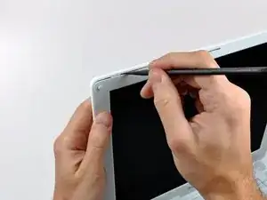
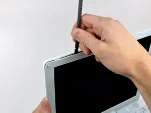
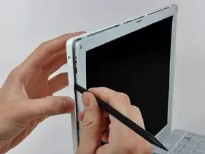
    • Insert the flat end of a spudger perpendicular to the face of the display into the gap between the front and rear bezels near the upper left corner of the display.

    • Rotate the spudger away from the display to pry the rear bezel off the front bezel.

  5. h1NiXRemDdW3moMs
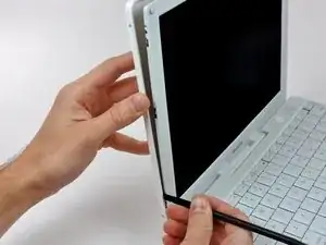
    • Run your spudger along the top edge of the front display bezel to evenly separate the two bezels.

  6. AkvK1yPDQjHTaXMN
    AkvK1yPDQjHTaXMN
    ZMycdwPDKD34tQ6J
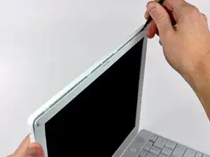
    • Working down from the upper left corner, use the flat end of a spudger to pry the rear bezel away from the left edge of the display.

  7. x6TaOFbQAwSGHHtV
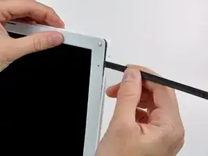
    • Use the flat end of a spudger to pry the rear bezel away from the right edge of the display.

    • If necessary, pry along the bottom edge of the rear bezel to separate it from the display assembly.

  8. jSKP3H2bXoXic6Kf
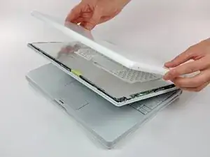
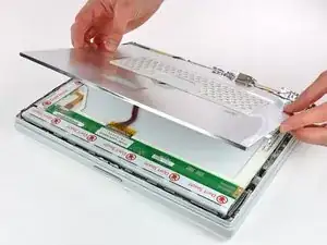
    • Lift the rear bezel off the display assembly.

  9. SeDecRIjq16Ls1O3
    SeDecRIjq16Ls1O3
    pegtTZLsMVatUHoZ
    • Close the display.

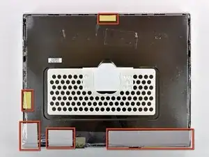
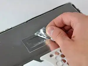
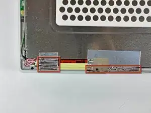
    • Remove the several pieces of tape securing the thin metal LCD cover to the display.

    • Carefully remove the piece of foil tape covering the display data cable connection.

  10. uR3pHhXE6QPSkJEP
    uR3pHhXE6QPSkJEP
    xlb1YlpGaiKIHyRg
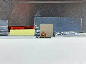
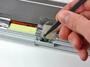
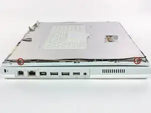
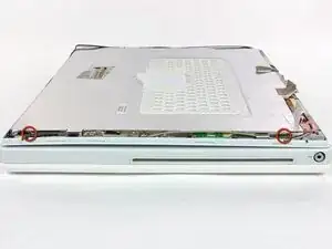
    • Remove the Phillips screw near the right display hinge.

    • Use the tip of a spudger to remove the small spacer under the screw you just removed.

  11. cxJXHSsRSvwCZYNq
    • Pull the foil/braided pieces of tape off the aluminum frame of the clutch hinges.

    • Leave the tape attached to the thin steel LCD cover.

  12. P1xwMUTs2CXNjQWR
    P1xwMUTs2CXNjQWR
    cChVLPbucBGBydOA
    • Remove the two Phillips screws securing the left and right sides of the LCD to the frame of the clutch hinges (four screws total).

    In some models can be more than four screws, they could be eight

    joecoolhh -

  13. 6A21ALaNsjYVoQvt
    • Carefully remove the thin steel LCD cover.

  14. caoQL3jHkXuyMwiB
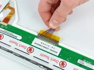
    • Disconnect the display data cable by pulling the cable away from the socket on the LCD.

  15. EcoU1kjMjdBqMItx
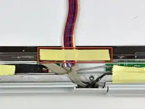
    • Remove the strip of yellow tape securing the display data cable to the metal LCD frame.

  16. Zv3TCBnyJTffnNU3
    Zv3TCBnyJTffnNU3
    gw4jB2nsISSFBKSd
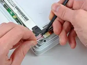
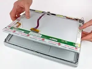
    • Disconnect the backlight cable from the inverter.

    • It is helpful to use a spudger to push the backlight connector away from its socket while you lightly pull its cables away from the inverter.

  17. NBeDQGpCsAicNauI
    • Lift the LCD out of the display assembly.

    • It may be helpful to press the latch release button and open your display slightly to push the LCD out of the display assembly.

  18. IwpmHcAHgfYMRHjK
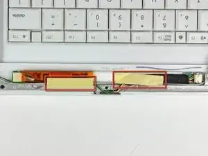
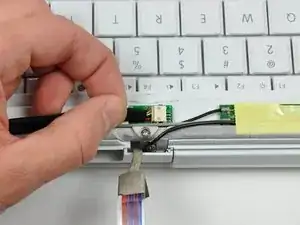
    • Remove the two pieces of yellow tape covering the inverter/AirPort cables.

  19. yRYwFQSB6Aky2oVf
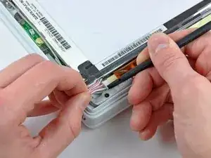
    • Disconnect the inverter cable by pulling its connector away from the socket on the inverter board.

    • The inverter board is a very thin and delicate circuit board that is easily broken. Use caution.

    • This connector tends to stick in its socket. It is helpful to push the connector with the tip of a spudger through the two small holes in the top of the socket while pulling the connector away from the socket.

    • Make sure to grasp the inverter cabling by the black tape and not the individual wires. Pulling the wires themselves will surely damage the inverter cable.

  20. IVbbF1XsXXQD4Kxs
    IVbbF1XsXXQD4Kxs
    nTnqdILPKa5FmNxw
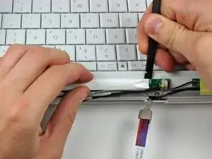
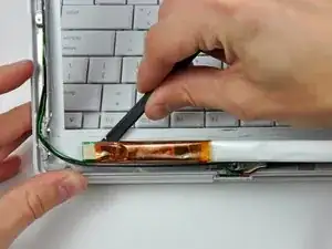
    • Insert the flat end of a spudger under the middle of the inverter board.

    • Slide the spudger to the far left and right edges to separate the inverter board from the adhesive securing it to the front bezel.

    • Remove the inverter board.

Abschluss

To reassemble your device, follow these instructions in reverse order.

Andrew Bookholt

578335 Reputation

Ein Kommentar

brilliant guide

carl -