Einleitung

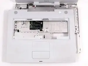
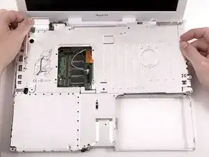
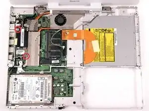
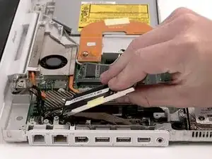
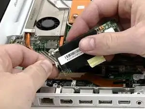
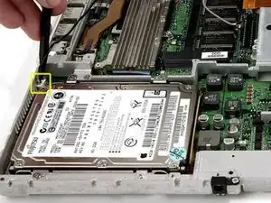
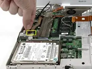
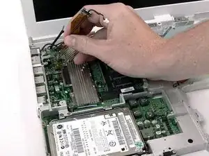
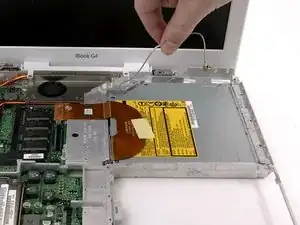
Change out the entire display assembly, including the inverter, Airport antenna, hinges and plastic casing.

  1. JOMi1v5lvH4bM2Up
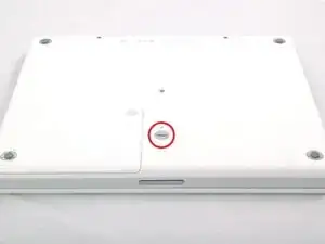
    • Use a coin to rotate the battery locking screw 90 degrees clockwise.

  2. sDUEOFFdDYPl4JYA
    • Lift the battery out of the computer.

  3. OShgOW4uVLDikm2d
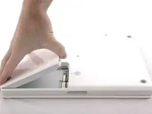
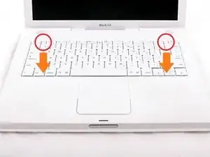
    • Pull the keyboard release tabs toward you and lift up on the keyboard until it pops free.

    • If the keyboard does not come free, use a small flathead screwdriver to turn the keyboard locking screw 180 degrees in either direction and try again. The locking screw is in between the F5 and F6 keys and is a clear piece of plastic.

    • Flip the keyboard over, away from the screen, and rest it face-down on the trackpad area.

  4. igRPdnpdBs2V5ial
    • If the computer has an AirPort card installed, follow the next three steps to remove it.

    • Push the wire clasp away from the AirPort card and toward the display, then rotate up to free it from the RAM shield.

  5. kgFadqVQi6M1q1Ku
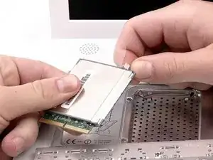
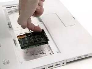
    • Grasp the clear plastic tab on the AirPort card and pull toward the display.

  6. Mgl4dIiwGOQODFxD
    • Hold the AirPort card in one hand and use your other hand to remove the antenna cable.

  7. QpKXiLu3r3HOrlDJ
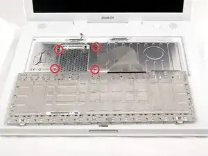
    • Remove the four silver Phillips screws that secure the RAM shield.

  8. qBKRySlvStdsLSRx
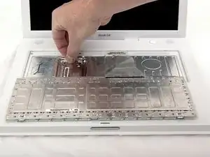
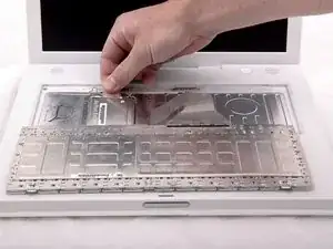
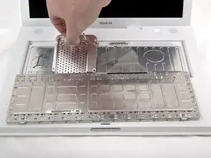
    • Grasp the metal bracket on top of the RAM shield and pull upward to remove the shield.

  9. E1OU2TEhhfVok3hE
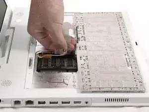
    • Pull the keyboard cable up from the logic board, holding the cable as close to the connector as possible.

    • Make sure that you reconnect the keyboard cable before replacing the RAM shield.

  10. FUyQvBOmxFHmaJ2D
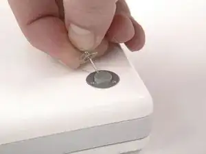
    • Use a pin (or anything you like) to remove the three rubber feet from the lower case.

    1.3 flathead screwdriver works better than a pin.

    Carlos Ferrari -

  11. mlM6SUeTposnLWJt
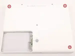
    • Remove the three newly-revealed Phillips screws.

  12. s5svYyRgiAlbvHwE
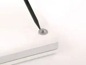
    • Use a spudger or small flathead screwdriver to pry up the three metal rings that housed the rubber bumpers.

  13. 4Pse1El2CwEMFYpl
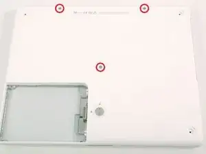
    • Remove the three hex screws using a T8 Torx screwdriver (or Allen screws using an Allen key if these are used).

    • The shorter screw is in the center of the computer.

    Why use a T8 Torx when these screws are metric hex 2? The T8 didn't work at all. Other than that this was a very easy repair. It cost $29 instead of the $150 that I paid the last time a Mac shop made the same repair.

    dalekaty -

    Zitat von dalekaty:

    Why use a T8 Torx when these screws are metric hex 2? The T8 didn't work at all. Other than that this was a very easy repair. It cost $29 instead of the $150 that I paid the last time a Mac shop made the same repair.

    Had the same issue with a T8, although I blamed that on my T8 being quite stripped. Finding an appropriate bit was quite a challenge... but I'm pretty certain a T8 isn't correct. The screws have a hex head, not a Torx... maybe T8 is the closest thing that tends to fit...

    Matt Falcon -

    The screw on the left wasnt able to get tight for some reason

    Helena -

    Not Torx, but allen key (British wrench), 2mm

    alicelittle -

    I attempted this last night following all the steps correctly, when I was done my ibook would not turn on. Now sure where I went wrong? Any ideas. Thank you

    stefanienikole -

  14. 3wHKRmCgZuoVDATH
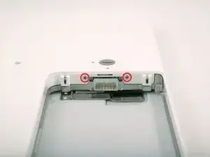
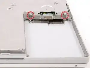
    • Remove the two Phillips screws on either side of the battery contacts.

  15. 5GIi5lYaZenrmgGP
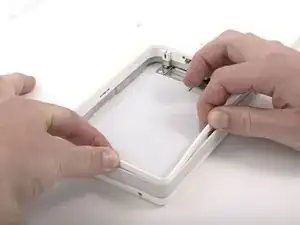
    • Breathe deeply. Trying times are ahead, but we promise the lower case does come off.

    • Push the thin rims of the lower case surrounding the battery compartment in, bending them past the tabs, and then lift up to free that corner of the lower case.

    I printed these instructions out, and this one was at the top of page 2. I found the first paragraph amusing enough that I had to show my boss.

    Kristoffer Bisher -

  16. 3ZtVbABr2uDA23P1
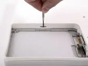
    • There is a slot on the wall of the battery compartment that locks the lower case in place. Use a small flathead screwdriver to pry out the slot's lower rim and pull up on the lower case to free the slot from the tabs holding it.

    • Be careful not to break this clip!

  17. PWPjlkidFoNcFyFY
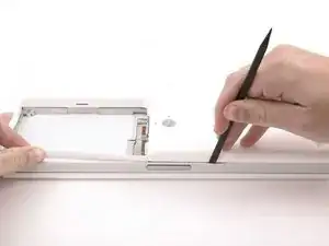
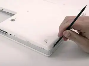
    • Run a spudger along the seam between the lower case and upper case on the front of the computer to free the tabs locking the lower case. Pull up on the lower case and continue to use the spudger as necessary until you hear three distinct clicks.

  18. mWMSQTBbG2oDVQYp
    • Continue to run the spudger around the front, right corner. There are two tabs on the port side of the computer, one near the front corner and one near the sound-out port.

    For me, this was really the toughest part! Trying to find/get a good grip on the iBook and really *forcing* that spudger around. All without scratching the display.

    bccreative -

    Once you loosen the the front the seam is very tight. I was able to slide the spudger in the middle of the port side instead of starting at the corner.

    Robert Oliver -

  19. fHNjk3GbLT5yWArL
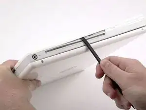
    • There are three tabs over the optical drive that must be released before the lower case can come off. Slide the spudger into the lower case above the optical drive and run it toward the back of the computer until you hear three distinct clicks.

  20. qcRKsrtmuvEmYgds
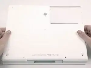
    • Once the front and sides of the lower case are free, turn the computer so that the back is facing you and pull the lower case up and toward you until the back tabs pop free (it may be helpful to jiggle the case up and down).

    This was the scariest part for me. I had to wiggle it a lot as it seemed to be stuck. But it did come loose.

    Robert Oliver -

    There are 4 tabs in the back. It'll come off easier if you use an spudger to release those.

    Carlos Ferrari -

  21. VLZquEv4CT3Q6BZd
    • Remove the small greasy springs with white plastic caps from either side of the battery contacts.

  22. FcORcLNdwO3QVZv3
    • Remove the following 10 screws from the bottom shield:

    • Six 3 mm Phillips

    • Three 7.5 mm Phillips

    • One 14 mm Phillips

    My 1 GHz iBook G4 only had the two 7.5 mm Phillips on the right and the two 3 mm Phillips above the battery compartment.

    geekspeak -

  23. YrJXr6CtLSFNwSVP
    • Lift the bottom shield off.

    The front of the foil cover has a lip divided into four separate tabs. Use a blade to loosen each as they can be easily bent.

    geekspeak -

    My dc board had 2 screws. for some reason when i tried to screw them both back in only one got tight. the other one just kept twirling so i left it out. i didnt want to have a loose screw rattling around in my computer.

    also had trouble laying down the wire to the dc board. it wouldnt lay flat but i was able to get it flat enough. overall it worked and the computer is now up and running!

    thank you! it was pretty easy

    Helena -

  24. VVvGfYLOaNsHsgQX
    • Remove the single Phillips screw securing the DC-In board.

    This is the first screw of the many on this part of the tear down that really needs the Phillips #00 screwdriver.

    turtlejp -

    At this point alternate hard drive can be connected to logic board for testing. Alternate hard drive and drive cable req'd. Remove hard drive cable from logic board. Plug in alternate cable and drive.

    A81Sturmer -

    My 1 GHz DC board had two Phillips, one on the far left and one next to the Z10B label.

    geekspeak -

  25. f5VNyWYgJgiCcPMN
    • Disconnect the DC-In cable from the logic board.

    My entire black woven cable cover was stuck down pretty well w/ 2x stick tape.

    bccreative -

  26. O3x4KoHveTiHsPGr
    • Deroute the cable from around the optical drive, removing tape as necessary, and angle the DC-In board out of its compartment.

    On this iBook, the DC board had a small Phillips screw on it.

    adamprall -

    Woops - never mind - neglected the screw from previous step.

    adamprall -

    Went pretty smoothly as described. I used an egg crate marked for each step where screws were removed to keep them all sorted out (OCD vs. old age). Only other tip was that in step #5 the rings and screws at the corners of the back seemed to be integrated and came out together, the rubber feet came up by pulling from the side - didn't really require a thumb tack. Otherwise, having the right tools (described) made it a snap.

    drscole -

    Zitat von drscole:

    Went pretty smoothly as described. I used an egg crate marked for each step where screws were removed to keep them all sorted out (OCD vs. old age). Only other tip was that in step #5 the rings and screws at the corners of the back seemed to be integrated and came out together, the rubber feet came up by pulling from the side - didn't really require a thumb tack. Otherwise, having the right tools (described) made it a snap.

    I agree - having the right tools is the key to this going smoothly. It would have useful to have more detail around where the long and short screws go on the heat shield. This is minor niggle and overall good instructions.

    jlwatts1 -

    Oops! I hit the wrong button. I did not mean to "Flag as inappropriate".

    geekspeak -

    Zitat von drscole:

    Went pretty smoothly as described. I used an egg crate marked for each step where screws were removed to keep them all sorted out (OCD vs. old age). Only other tip was that in step #5 the rings and screws at the corners of the back seemed to be integrated and came out together, the rubber feet came up by pulling from the side - didn't really require a thumb tack. Otherwise, having the right tools (described) made it a snap.

    The egg crate is a good idea. I use a piece of cardboard and I label each step and layout the screws visually as I pulled them out.

    geekspeak -

  27. A4swCUOKSxRYBYRX
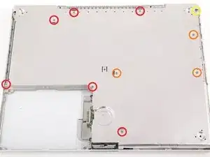
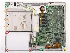
    • Remove the following 11 screws from the bottom of the computer:

    • Three 3 mm Phillips around the battery compartment. (Some models may only have two screws.)

    • Three 4.5 mm Phillips along the optical drive bezel. (a magnetic screwdriver may help to lift these screws out)

    • One 11 mm Phillips in the lower right corner. (if present)

    • Four 14.5 mm Phillips.

    The middle screw along the optical drive got sucked sideways into an opening by something magnetic and proved impossible to get out with a bit of blutack on the end of a screwdriver. In the end turning it over and giving it a smart tap worked.

    tatterjack -

    - the 3 red screws located around the battery compartment are absent. (I never opened my

    G4 before).

    - the 3 orange screws along the optical drive bezel are deep located and I can't see where to

    place the screwdriver. By trying I run the risk to damage the screw head.

    su40 -

    I realized that there are no screws 3 red and3 orange, the are only 4 green ones and a yellow one.

    su40 -

  28. TokcYw3KkLj4OipZ
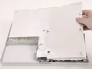
    • We recommend placing the computer on a soft cloth from this point on to prevent damaging the logic board.

    • Turn over the computer and open it.

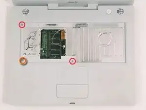
    • Remove the 2 Phillips screws (3mm) from the edges of the keyboard area.

    • Remove the 4 mm Phillips screw from the lower left corner.

    bottom right philips head screw removed just fine. Upper and lower left don't seem to fit any of my philips screwdrivers. What size are those screws?

    jimryan -

    The "two 3mm" screws are actually 4mm and the 4mm (orange) is the 3mm

    tjod -

  29. xboCDBELJQJOMD1a
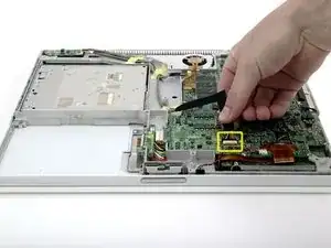
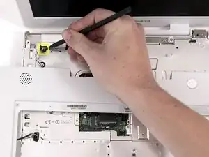
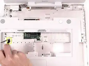
    • Before you can yank the upper case off, you must disconnect the trackpad connector, the blue and white power cable, and speaker cable as described in the next steps. Be especially careful with these cables; never pull directly on the cables, but use a spudger to pry up the connector directly.

    • Lift the upper case and use a spudger or your finger to disconnect the trackpad connector hidden beneath the white plastic tab. Due to model variatons your trackpad connector may be different than the one pictured.

  30. axnVTAlkcDeEgQxG
    • Carefully lift the upper case about half of an inch and move it so that you can access the power and speaker cables.

  31. MQ5kXQoR4OGZ1fuh
    • The connectors at the ends of the cables are attached very firmly to the sockets on the logic board. Pulling directly on the cable will either separate the cable from its connector or the socket from the logic board.

    • Lift the upper case enough to disconnect the blue and white power cable from the logic board. Using your fingernails or a dental pick, carefully pry the connector from its socket. Make sure you're pulling only on the connector and not on the socket.

    I have pulled it off, now what?????

    Ester -

    I have fixed it!! Whooohooo!!

    Bought a soldering bolt and wire, and fixed it in 10 minutes myself, I'm so proud of me..... ;)

    But I hope I won't have to open it again! And the 3 screws which are left.... hmmmm never mind. :D

    Ester -

    Yup. Take off that shield first. I'm lucky my father in law is good at soldering, because I'm not, and that power switch connector fell off the moment I touched it....

    Jaddle -

    I skipped this and the next step altogether. Instead of taking the risk of breaking the power and/or speaker sockets, I left them connected. I put a stack of big books just to the left of the iBook. I swiveled the top case off and let it lean against the books. I removed the top shield and carefully swiveled it off and to the left, so it is now leaning on the top case. I had to move the power cable out of the way, and re-orient the top case so it's resting on it's back edge while the shield was resting on it's left edge. Then I slid the iBook towards the edge of the table and disconnected the HD ribbon from below! I then proceeded with removing the HD and putting in the new one.

    Hilal Malawi -

    When putting the rings back you will need to figure out their correct orientation. Just rotate each ring until you find the position that will make it flush with the case. There are three possible positions but only one of them is the right fit.

    Hilal Malawi -

    As the other comments make plain, you can't overemphasize that the power connector is in tight, and it is much easier to pull the connector off the board. That's what happened to me -- I'm really bad at soldering, so I will be looking for a replacement board. Oh well.

    Don Solomon -

  32. l5tM5MlEHRyImgIQ
    • Carefully disconnect the multicolored speaker cable from the logic board. As before, make sure you're pulling only on the connector and not on the socket.

    these connectors can be very loose and break from the logic board. I have left this one connected until after the next step, at which point I can pull it out more carefully and easily.

    -Dan "The Berkeley Mac Guy"

    Dan Fries -

    I second Dan's method. The top shield makes it impossible to pry between the connector and its socket. The socket is so poorly affixed to the logic board that you must be very careful to apply leverage between the connect and socket.

    Kent -

    now you tell me!! So then what if you have pulled it off? How very depressing.

    anakowi -

    If you pull it off, find a place that does micro-soldering. What a pain!

    Check your local Chinatown, you might find someone who worked in an electronics factory, like I did. Or scrap the thing and check on craigslist.org for a replacement.

    Dan Fries -

    haha - doubt I will ever open up this baby again. That was gruelling. Lucky it was only the built-in speaker cable - I use headphones or a portable speaker if I need sound now.

    anakowi -

  33. tcIrRlLE6PxJZkoK
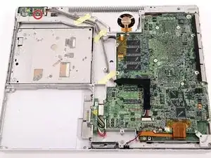
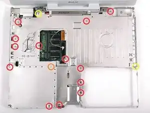
    • The screw circled in orange may not be present in some models.

    • Remove the following 16 screws:

    • Thirteen 3 mm Phillips.

    • One 3 mm Phillips. (actual screw not present in image)

    • Two 4 mm Phillips.

    • Be sure to fit the screw near the left hinge through the loop in the display data cable, securing the cable to the upper case.

    • Missing in this photo is the Bluetooth antenna present in some iBooks. It is located at the upper right corner of the battery compartment, just above the 4mm screw. You can see the bracket for the antenna in the photo. It is the two I-shaped holes just above the 4mm screw that must be removed in this step. To remove the antenna, slide it toward the LCD, and tilt it vertically back towards yourself.

    Missing in this photo is the Bluetooth antenna present in some iBooks. It is located at the upper right corner of the battery compartment, just above the 4mm screw. You can see the bracket for the antenna in the photo. It is the two I-shaped holes just above the 4mm screw that must be removed in this step. To remove the antenna, slide it toward the LCD, and tilt it vertically back towards yourself. In the next step, where the shield is removed, you will need to slide the antenna through the lower I-shaped hole.

    Sean Brannon -

  34. LqCWsXYtapS6j2cL
    • Lift the top shield up from the right side, minding the upper left corner, which may catch on the metal framework.

    • If your iBook has Bluetooth, as discussed in the previous step, you will need to slide the antenna through the lower I-shaped hole in the shield before completely removing the shield.

    The shield on this iBook had a small sensor threaded through the opening directly above the battery compartment opening, on the right near the edge of it. I just carefully threaded the sensor through that hole in order to remove the shield.

    adamprall -

  35. qJhmmNfLFGZLSiYj
    • Due to variations between iBook G4 models, your modem may look slightly different from the picture. All of the following steps apply to either model.

    • Remove the two Phillips screws at the corners of the modem.

  36. uqHvglHwBKtQRcKv
    • Lift the modem and modem shield from the bottom.

  37. EUHxUZMtpVqGrRXC
    • Disconnect the RJ-11 cable from the top of the modem.

    • When replacing the modem, first make sure that both the microphone and display data cables are routed beneath where the modem lies.

  38. mgxEQdfA6bLLkJTy
    • Turn the computer over.

    • Disconnect the inverter cable from the logic board and deroute it from the metal framework, removing tape as necessary.

  39. HZBtuHWRJqVoENQC
    • Turn the computer back over.

    • The cable you're about to remove is very fragile - do not pull directly on the wires. Instead, try to pry up the connector directly, using a spudger or a small flathead screwdriver if necessary.

    • Disconnect the microphone cable at the front of the computer, between the left side of the hard drive and the metal framework.

    The side of the case has a alight recess that the connector fits in. Pulling the case out lets it come out more easily.

    tatterjack -

    Zitat von tatterjack:

    The side of the case has a slight recess that the connector fits in. Pulling the case out lets it come out more easily.

    tatterjack -

  40. 4RykdhCaGZtMOdWo
    • Use the black plastic loop to disconnect the display data cable from the logic board.

  41. oCJ3lKKYeBPu1HpM
    • Deroute the microphone and display data cables from the metal framework, removing tape as necessary.

  42. 4itW2ocs1XixEqYa
    • Deroute the AirPort antenna cable from the metal framework, removing tape as necessary.

  43. xaQBjixGTmanYhtm
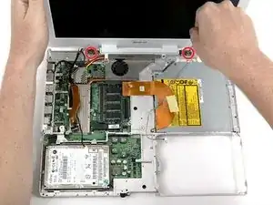
    • Support the display with one hand and remove the single Phillips screw on either side of the hinge (two screws total).

    • The screws go in the outer holes on each side (you can see the threads in the correct hole).

  44. Ds6QU25fEQJQDkOs
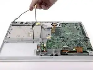
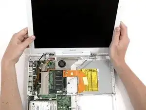
    • Lift the display up and tilt it backwards, freeing it from the two metal alignment posts holding the hinges in place, and slide it away from you.

Abschluss

To reassemble your device, follow these instructions in reverse order.

iRobot

Mitglied seit: 25/09/09

0 Reputation

Ein Kommentar

Very nice guide, thanks!

I call this the “You Gotta Be Kidding Me” Era of Mac repair. The Flat Panel iMac, the iBooks… good times. If I actually get the iBook G4 running I will be most happy to update this comment.
Boyd Waters -