Einleitung

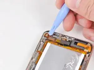
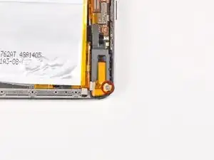
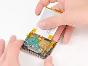
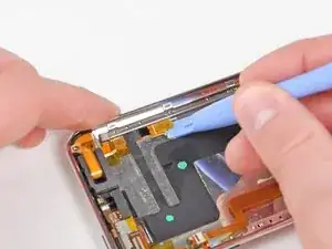
This guide shows how to replace the rear panel on the 3rd Generation iPod Touch.

  1. AK61uLs34Ai1bUBi
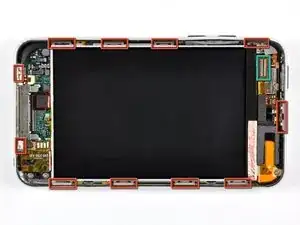
    • The glass front panel on the third generation Touch has a plastic frame glued both to its outer edge and also under the wide black strips at the top and bottom of the device.

    • The picture at left (front panel already removed) shows the locations of the metal clips (shown in red) that snap on to the plastic frame. In the next few steps, try to pry the front panel up from the gaps between these clips.

    • Also, be mindful of the very thin and delicate touch screen ribbon cable (connector location shown in green) attaching the front panel to the upper left corner of the Touch.

    Do be gentle when snapping your replacement front panel back on your iPod. There is potential for the Home button to be “squished” up against the internals and thus unable to be pressed in. If this happens, you must pry the panel up enough to let the Home button clear all the parts behind it and leave room to work.

    Matt Rausch -

  2. qFlgY3FdyMHoNgHs
    qFlgY3FdyMHoNgHs
    QHtswJOFonfxmAsS
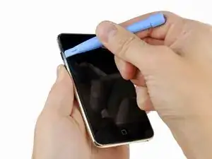
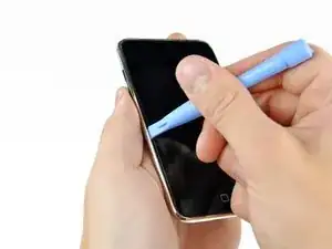
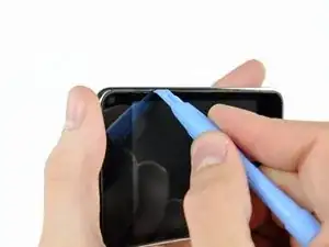
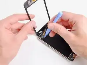
    • Gently insert an iPod opening tool between the glass front panel and its plastic surround near the volume adjust buttons.

    • Rotate the tool away from the Touch to pry up on the glass panel.

    • The key is to work slowly and gently to avoid breaking internal components.

    This is a poor place to start. You risk damaging the volume control. It makes more sense to start at the bottom, at the Home button, where there is plenty of room and nothing to damage.

    Esmond Pitt -

  3. IGWB4pXI1HcQnjjq
    IGWB4pXI1HcQnjjq
    N1rEsG6BVFhYpe1K
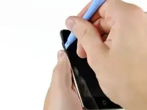
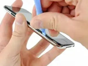
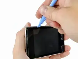
    • Insert the iPod opening tool between the front panel and its plastic surround and pry up at several points along the left edge of the Touch.

    • Do not insert the tool and run it down the edge of the front panel, as it will damage the front panel itself and the rubber strip along the plastic surround. It is best to work at one point, pry up, then remove the tool and reinsert it at the next spot to be pryed up.

  4. dtPaaMEouxBdduA2
    dtPaaMEouxBdduA2
    2V5IlTNojTldQZwk
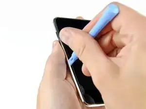
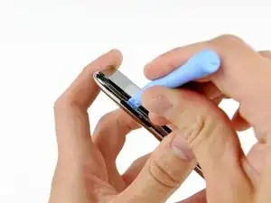
    • Continue prying up the left edge until the top and bottom edges start to lift out of the Touch.

    • Once the top and bottom edges have lifted slightly out of the Touch, use the opening tool to assure the plastic surround is detached from the clips along the inside of the Touch.

  5. rYgfjiSwJsIWJMdm
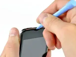
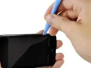
    • Continue the prying procedure, now focusing on detaching the plastic surround from the internal metal clips.

    • Pry along the top edge of the Touch to further separate the front panel from the rest of the device.

  6. xldCQmjOG2JsFtmg
    xldCQmjOG2JsFtmg
    OQ6KETBADwy1hVFw
    t1vukwXndiSOwQy6
    • Pry up the front panel along the right edge using the method described in previous steps.

    • Eventually work around the entire perimeter of the front panel until it is lifted slightly from the rear panel.

    • Also, ensure that the plastic surround is separated from the clips in the rear panel.

  7. XbF3gSGrkor4mCir
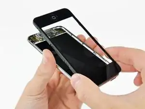
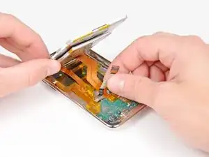
    • Lift the front panel out of the rear case minding the cable still attaching it near the upper left corner of the Touch.

  8. e22uRmeUMNtPONkT
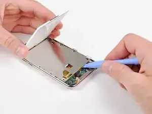
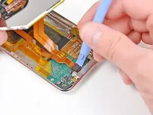
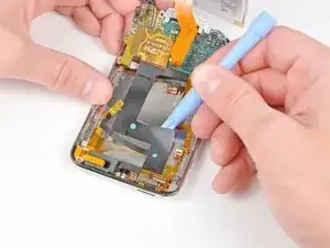
    • Use the flat end of a spudger (or an opening tool) to very carefully pry the touch screen cable connector up off the upper logic board.

    • The touch screen ribbon cable is extremely fragile! Be very gentle in disconnecting this cable to prevent tearing the ribbon cable.

    • Now that the front panel is out, check it for damage. If the plastic surround is not flush with the front face of the glass panel, gently peel it off and stick it down.

    • Be careful not to scratch the front panel on the underside of the black portions, as the scratches will be visible once the device is reassembled.

    • Be sure to clean both the face of the display and the inner surface of the front panel, as any dust or fingerprints will be trapped inside the Touch once it is fully reassembled.

    I had a real challenge getting the ribbon cable connected; after 20 minutes of trying while carefully balancing the front panel and trying not to rip the ribbon, I grabbed the old screen, ripped off the connector and practiced getting it on.

    I had another challenge of the connector staying on...I had noticed a little piece of rubber had come off when I took the old screen off. That piece of rubber was EXACTLY the same size as the connector; I'd guess it is meant to hold the connector in place when the panel is put back on...So, I put it on top of the connector and closed it up..

    Perfect!

    Cheers, Rob

    rledwa2 -

    This was where I messed up, the adhesive on the digitizer was weak and when I tried to remove the original the bracket stayed in place, I figured that as I was installing the replacement and as I tried to put it into place and it wouldn't go I apparently jerked and broke the ribbon cable on the replacement there went my money now I have a faceless unusable iPod until I can order another, I did replace the LCD with little trouble though, not a completely failed repair.

    kcbennett -

  9. CZKEh2DFhbpXp4hj
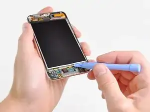
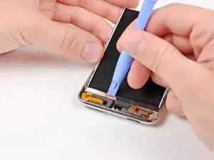
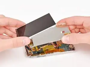
    • Insert a small iPod opening tool with the edge angled up toward the underside of the display between the white plastic backlight and the metal shield beneath it.

    • Pry up along the lower edge of the display enough to grab it with your fingers, being careful to not flex the screen.

  10. hU2O4te5w1Rq1sf1
    • Lift the display up from its lower edge and rotate it toward the top of the Touch.

    • The next few steps require removal of components under where the display normally sits. Be sure to hold the display to avoid putting tension on the delicate display ribbon cable.

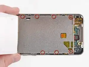
    • Remove the seven Phillips screws securing the metal display tray to the rear panel. They may be very tight; watch carefully to make sure you don't strip them.

    • The two darker screws belong in the two holes in the tray nearest the bottom edge of the Touch.

  11. qlXLnosEdWpCpDDa
    • Lay the display back down into its tray.

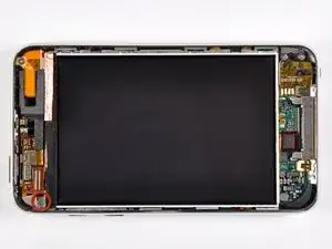
    • Remove the final Phillips screw securing the metal tray to the rear panel.

  12. dZGiyfhSqqCriULB
    • Lift the display out of the metal tray and rotate it toward the top edge of the Touch.

    • Use an iPod opening tool to lift the metal display tray and rotate it up toward the top edge of the Touch.

  13. CAN1JSNhHqoVuppB
    • Use the edge of an iPod opening tool to peel the copper tape off the top edge of the display.

    • Leave the copper tape attached to the metal display tray.

  14. cTJQCi4XB4K3bnoQ
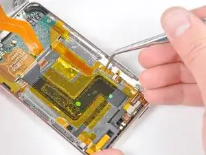
    • Use the edge of an iPod opening tool to remove the piece of tape covering the display data cable.

  15. cTb24PdotTCtmYVs
    • Use an iPod opening tool to pry the display data cable connector up off its socket on the logic board.

  16. oOaUb4tc3EiJGypu
    • Peel the display data cable off the adhesive securing it to the rear panel.

  17. ySZEyIeMkmtN4bR5
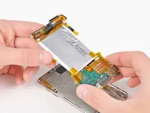
    • Lift the metal display tray slightly (the battery is attached to its underside) and remove the display from the Touch, minding its delicate cable that may get caught.

    • The display ribbon cable is routed under the metal display tray.

  18. oEvLAh2aQbPlu6KW
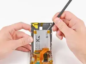
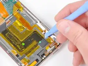
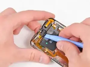
    • Use the flat end of a spudger to pry the battery off the adhesive securing it to the metal display tray.

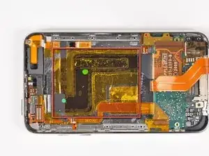
    • Remove the metal display tray and set it aside.

    • Lay the battery flat in the rear panel.

  19. mbMcsnZVY4KXCYwc
    mbMcsnZVY4KXCYwc
    ORHhkDjHiIrxTRSP
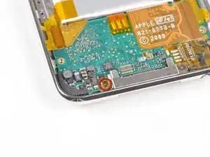
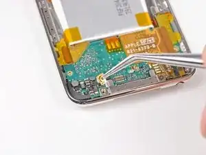
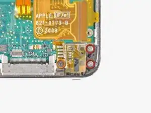
    • Remove the single Phillips screw securing the gold pressure contact to the logic board.

    • Use a pair of tweezers to lift the Phillips screw out of the logic board.

    The golden Contact was broken while my assembling? Is the a possibility to buy the article separately?

    joachimschreiter -

  20. BoKc1flsnRMakLif
    • Remove the following three Phillips screws securing the logic board to the rear panel:

    • Two 2.3 mm screws

    • One 1.9 mm screw

    • The darker screw belongs in the screw hole next to the dock connector.

  21. RFbMRWfnSSM4nKYb
    RFbMRWfnSSM4nKYb
    1BJ2LNrB3q5kuInJ
    • Using the edge of an iPod opening tool, flip up the control button ribbon cable retaining flap.

    • Be sure you are prying up on the retaining flap, not the socket itself.

    • This socket is found under the battery.

  22. FSXVZKNMty2LY3bm
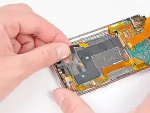
    • Carefully remove the two large pieces of tape securing the ribbon cables to the rear panel.

  23. fvWYBVD1mhtyUahj
    • Use the edge of an iPod opening tool to peel back the protective rubber grommet to reveal a hidden Phillips screw.

    • It is not necessary to completely remove this flap.

    • Remove the hidden Phillips screw.

  24. a5XIkhLqXklX6lIU
    • Remove the remaining Phillips screw securing the upper logic board to the rear panel.

  25. DfNENhtGrHCpkR1W
    • Carefully pull the lower logic board away from the lower edge of the rear panel.

    • Allow the edge of the logic board to rest on the outer edge of the rear panel.

  26. kWhQEO2PSrQpNtdV
    kWhQEO2PSrQpNtdV
    CIPCwkqfxnDHtjWU
    • Use the edge of an iPod opening tool to carefully free the antenna connector cable from the adhesive securing it to the rear case.

    • Use the edge of your iPod opening tool to disconnect the antenna cable.

  27. xyhRqZkA1pF2pN3j
    • Carefully peel the antenna cable off the adhesive securing it to the rear panel.

    At some point before this (step 27), the ribbon cable from the lower logic board to the volume control switches was disconnected, at the socket near the switches. This can be seen in the lower center of the figure. If it's not eventually disconnected, the logic board assembly cannot be removed in the last step.

    user2048 -

  28. vrDneelrHvwmN2te
    • Remove the small strip of tape securing the antenna socket ribbon cable to the rear panel.

  29. CpH3CKnf5OuQQA4U
    • Use the edge of an iPod opening tool to peel the antenna socket ribbon cable off the rear panel.

  30. IFJCSUC5isgvQpux
    • Use the edge of an iPod opening tool to carefully peel the Wi-Fi ribbon cable off the adhesive securing it to the rear panel.

    • Do not excessively strain the cable, as it tears easily.

  31. gBeB5NSSK2imlj2B
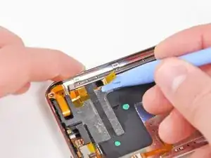
    • Use an iPod opening tool to pry the black plastic frame under the upper logic board up from the adhesive securing it to the rear panel.

  32. WLVXLVDyURxHchOI
    • Carefully remove the logic board assembly from the rear panel, minding any cables that may get caught.

  33. yPxFdqRb4JPNMxnj
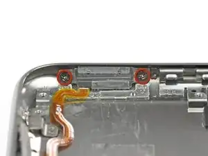
    • Remove the two Phillips screws securing the power/volume controls to the rear panel.

  34. aybyDg5WktyHEpUH
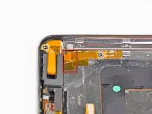
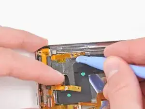
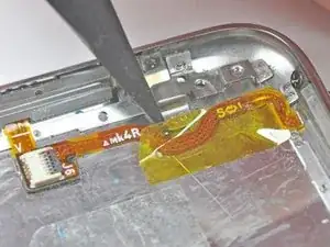
    • Use the tip of a spudger to remove the yellow kapton tape covering the power/volume control ribbon cable.

  35. poH165Rm6K5IO2BC
    • Remove the two Phillips screws securing the power/volume controls to the rear panel.

    • Lift the power/volume controls out of the rear panel.

  36. YqyEXPcKOvPt3kXH
    YqyEXPcKOvPt3kXH
    pwxZfbsGhBDKqTEm
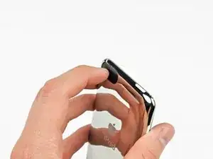
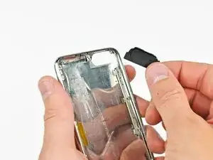
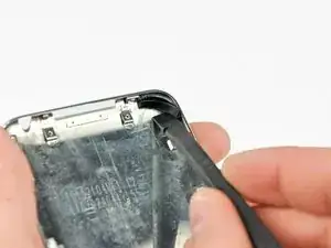
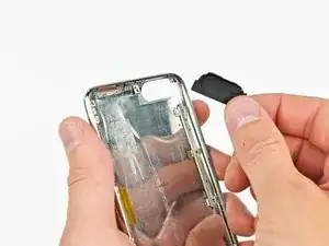
    • Use your finger to push the plastic antenna window through the other side of the rear panel.

    • Remove the plastic antenna window from the rear panel.

  37. 2pES3s2FHqjGXF4v
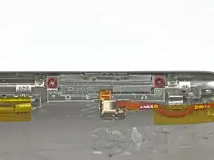
    • Use the flat end of a spudger to pry the protective rubber grommet from the bottom left hand corner of the rear panel.

Abschluss

To reassemble your device, follow these instructions in reverse order.
Andrew Bookholt

578335 Reputation

0 Kommentare