Einleitung

  1. O3Z3TrvYDISKlgyR
    O3Z3TrvYDISKlgyR
    M2RqlJZWPYVJeBfb
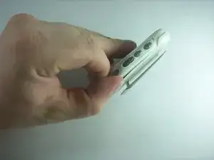
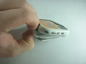
    • Remove the belt clip by pulling the clip casing up and away from the device starting at the top over the slightly protruding headphones jack.

  2. fXBCqkdFC5csW65Y
    fXBCqkdFC5csW65Y
    IyNCGvHGlOwEN4KM
    UDMsgJfQQZoBcXYy
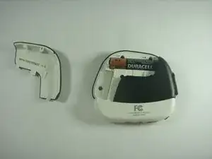
    • Remove the battery cover by gently pushing inward on the arrow on the cover.

    • While maintaining pressure push the cover upward.

  3. UyJ3PGMZEZChCXwy
    UyJ3PGMZEZChCXwy
    aAWHvXtOf6cyAAID
    • Remove the Battery from the socket

    • When installing the battery take note of the signs displayed in the socket to determine which direction the negative and positive ends should be.

  4. U1X2CWAE4dYJWEIg
    U1X2CWAE4dYJWEIg
    XRodYkynQosCSp2E
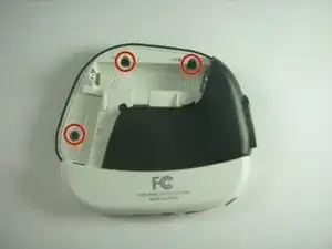
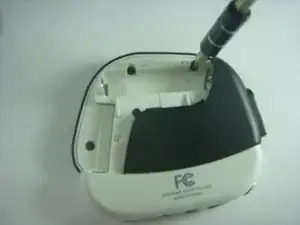
    • Under the cover you will find Three (3) 5mm screws that will need to be removed. For this you will need to use the PH00 screw tip included in your iFixit kit. Make sure to keep track of these screws as they will need to be reinserterd during the reassembly of your device.

    • These screws are different from the two other screws from the interior

  5. UQm1mDN2IcKlORkT
    UQm1mDN2IcKlORkT
    LbVDnxn2VC3Jb1F5
    pQOi1CnhJ3bbXtbv
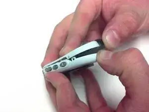
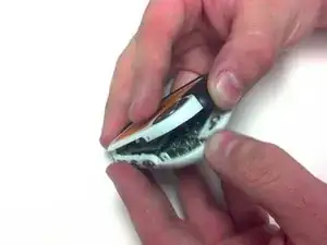
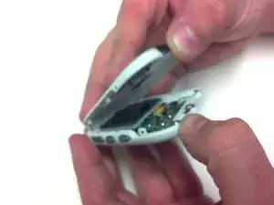
    • Separate the front housing from the back housing using your thumbs. Carefully pry around the edge of the bottom of device then be sure to unhook the clip inside just below the hold switch.

  6. sQtt2w6gAHPHHBpH
    sQtt2w6gAHPHHBpH
    CSYbsxWZupScyQeC
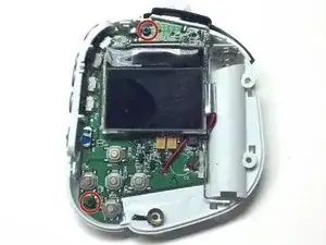
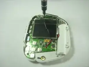
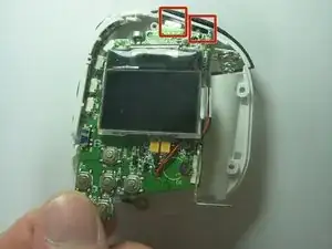
    • Once you have removed the front housing and exposed the internal board and screen locate and Remove the Two (2) 4mm PH00 screws on the board.

    • One is located in the top middle above the screen and the other is located at the bottom left between the Stop and Back buttons.

  7. 6ZFFQnFLOTBbTiHN
    6ZFFQnFLOTBbTiHN
    MKvOXgBgBLEIcxyr
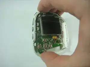
    • Once those screws are removed, gently remove the board from the rear casing.

    • When installing the motherboard into the case be especially careful with the headphone and USB jacks located at the top of the motherboard. These should be slid into their sockets first.

  8. tcOjLwlXOgsJhM5A
    tcOjLwlXOgsJhM5A
    3UWdiwGUk3tvVT6Z
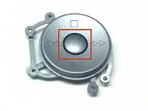
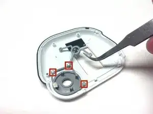
    • There are two parts to the face button panel. The center button or Enter is held on by three pins at the top left and right sides and at the bottom left side of the panel; when you're looking at the device from the inside.

    • Use the bit spanner bit tool to gently pull upward on each of the arms to remove them from the pins.

  9. gK5qLaTCjwsxaWIy
    gK5qLaTCjwsxaWIy
    LWjJUuYvXv2UpmWv
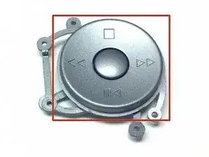
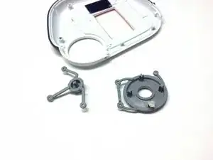
    • The main plate of the face buttons is held on by Three arms on pins.

    • You must first have removed the center button from the pins to access the main plate where it is attached to the same pins.

    • Use the bit spanner bit tool to gently pull upward on each of the arms to remove them from the pins.

  10. YWROmccEU1ZBBBE3
    • All pins that hold the arms of the center button and the main plate of the face buttons have a slight flange at the top acting to hold the arm sockets. This is designed into the device at manufacture and removing the arm sockets will deteriorate the flange.

    • If removing the buttons for replacement is necessary then after replacement achieving a similar flange may be possible by tapping on the pin after replacement of the arm sockets with the butt of the screw driver. This might not work though as the pins on our ilo broke off during button removal.

Abschluss

To reassemble your device, follow these instructions in reverse order.
tjkurt01

Mitglied seit: 04/06/13

306 Reputation

0 Kommentare