Einleitung

  1. Om1LfWVSrFcOuBUc
    Om1LfWVSrFcOuBUc
    ptAUTW23wda22bS2
    EqtoXJbjj65LvV4E
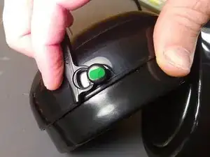
    • It is much easier to insert and remove the muff body clips by rotating them 90°. The plastic stud underneath is oval in shape and is indicated in green on the image.

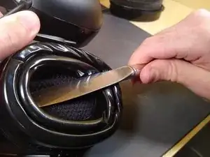
    • Remove the pad by inserting a large flathead screwdriver or butter knife just underneath the plastic backing plate of the padding and continuing all the way through to the muff shell. Then twist forcefully, and the underlying plastic should pop off. Using a finger is nearly impossible on the first attempt, but works on subsequent attempts.

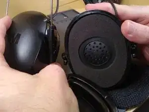
    • Now it's free! But be careful to not twist or yank the cable.

  2. ZRKKclKDoIawPJMb
    ZRKKclKDoIawPJMb
    XWDSTOREU6fGAmPn
    JxhORHSZceV6P5Cn
    • Take a T7 bit (thanks Laz) and start opening it up.

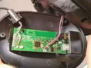
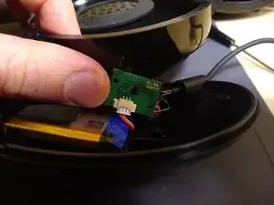
    • The backside view of the earcup shows the circuit board. There is a cavity on the ear cup, but it looks to only be as deep as necessary. Wires going to the speaker are strain relieved with glue (not pictured)

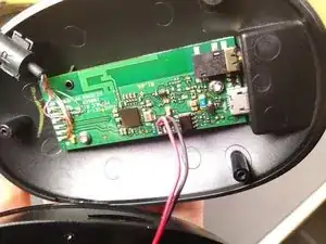
    • Another view shows the BES2000 SoC

    • The ordering of the colors of the wire: Blue-Gold, Green, Red-White, Blue, Orange, Red. Thanks Grant!

    What is the order of the 6 colored wires in the right ear cup, from top to bottom? Glare in the picture makes it difficult to see.

    Zach MacLurg -

    I no longer have the headphones actually, so I can’t tell you. You might want to try increasing the color in a photo editor. Did yours get ripped out or something?

    nolanhergert -

  3. JVrx1sytyA63pfFR
    JVrx1sytyA63pfFR
    hSUjvsTyvPCBLBtg
    CTFvZtRIMCtkASHx
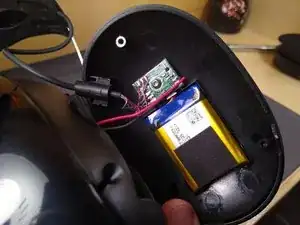
    • Contains a battery and connector PCB. Battery type is 603040 lithium ion, dimensions are 6mm thick X 30mm tall X 42mm wide, with a 3-pin JST (includes thermistor apparently)

  4. GoDJXViOeTpWLQtS
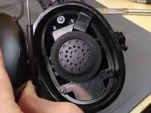
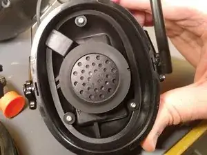
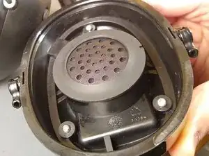
    • The left side speaker and its cavity are 37mm wide and 16mm deep. There is extra space underneath the speaker, maybe for better acoustics. The rubber gasket is glued on. The right side had a similar cavity, although not as deep.

    • Proper earpad replacement cups are GEL-HYG (specific to WorkTunes). Peltor-style replacements don't work for some reason.

nolanhergert

Mitglied seit: 05/10/11

109 Reputation

23 Kommentare

How about the headband? Is it replaceable? Or maybe the ear cup tip?

RobCow -

I don't know if you can find the headband as a replacement part. However, the gel ear cups are replaceable. Just look for 3M Peltor Gel Ear Cup replacements.

nolanhergert -

Replacement gel cushions for PELTOR style headphones such as the Optim 105 do not work. The size is different. There are 3M WorkTunes specific replacement gel cushions available from 3M (part no. GEL-HYG). I purchased two spare sets of genuine 3M WorkTunes replacement gel cushions on Amazon back in March 2022 when they were clearing them out for USD$12.73/each. Since I already had a pair of Optim 105's, I thought I might see how they work with them and perhaps get a set for them too (I have two pair of WorkTunes hence a set of spares for each). Found out they do not fit the Optim 105's and the product description on Amazon shows what models are compatible.

robert -

Thanks Robert. I forget where I read that.

nolanhergert -

Hey, did you ever repair your headband? I see replacement options on ebay but can't find any info on doing the swap anywhere

Ray Coburn -

could someone tell me where i could find the wire that connects the two shells together. I know the wire has 6 conductors and its outside diameter is 2.6mm or .102''. mine is broke. thank you.

Stéphane Tougas -

I don't know of an exact replacement, 3M doesn't look to list anything. Part of the difficulty of replacing it is that the rubbery "block" that holds the cable in is injected molded around the cable. But if you're willing to MacGyver, hot glue and some 6-conductor cable from Amazon (fast shipping, but kinda thick 28awg https://www.amazon.com/Striveday-conduct...) or AliExpress (30awg, but takes a month to arrive, https://www.aliexpress.com/item/22558003...) should work fine. Going the MacGyver route, I don't think the thickness will matter that much. Good luck!

nolanhergert -

Can someone tell me the order or the 6 wires in right side circuit board from top to bottom can’t tell in pic thankyou

Roger Thibeault -

Need the color code order of the 6 wires that go in right ear to circuit board from top to bottom

Roger Thibeault -

Referencing the picture (with upside down text on the board), Top -> Bottom:

Blue-Gold

Green

Red-White

Blue

Orange

Red

At least that's what mine is. Not a lot of extra wiring, may need to provide a jumper wire (I used 28 AWG and it works fine).

Grant -

Need the color code order of the 6 wires that go in the left ear to circuit board.

Regards, Denis

d_de_chantal -

Can someone tell me what size bit is needed to remove the three screws? Thanks

Andrew Sims -

They require a small Torx. It has been a while since I took mine apart to repair charging port that came off the board but it was somewhere between a T-5 and T-9 size. I didn't really think about the size because I have a large set of various driver bits to repair electronics and I just went through the small Torx ones in the 5-9 range until I found one that fit.

robert -

It's a Torx T7 bit.

Laz -

I forgot to say, to the author of this teardown: thanks, the dimensions of the speakers totally helped me out! If you can solder they are easy to replace and the new ones I put in mine sound great!

Laz -

Great! I see I didn't specify where I measured it, but it looks like I could only measure the outer edge easily. What size did you end up buying and having it work well? 35mm?

nolanhergert -

Do you know of any mod that would allow audio-in to play over the Bluetooth audio? Normally the jack can only play if Bluetooth is paused or disconnected. I'd like to use both at once so I can monitor a two-way radio at the same time.

If you have any ideas about workarounds for this I'd appreciate you sharing them.

Charlie -

What about routing the wires from the audio jack to permanently go to the speakers? You'd have to test which connections exactly are needed. Referring to this image (https://guide-images.cdn.ifixit.com/igi/...), basically one wire would go from one of the soldered pads on the audio jack in the top right to the red speaker wire pad on the bottom, and another would go from another jack pad to one of the colored wires on the left side. Hope this makes sense!

nolanhergert -

Thanks! I'll give this a shot and report back.

Charlie -

Mine stopped charging. Thanks to this guide I got mine open and found one of the wires had pulled free from the solder. See the photos - I soldered it back on and hot glued it all in:

https://imgur.com/a/GxgRGPi

Jayden Lawson -

I think I’ve pulled a little wire going into the earpiece - because the Bluetooth says it’s connected, but it wont play. Can a pulled wire be reconnected…or am I wasting my time?

wernerott10 -

Yep, pretty doable, even for someone new to soldering. The comment above this has a good picture of what the inside looks like and the small wires you will need to deal with.

If you don't know anyone handy with a soldering iron (works on cars or electronics, robotics club), a ~$10 adjustable temperature kit on amazon with multiple tips is useful for other things too (plastic welding comes to mind). Maybe this one? https://www.amazon.com/MeFix-Soldering-T...

nolanhergert -

It's definitely possible. If you want to learn soldering and plastic welding, then pick up a $10 soldering kit on Amazon with multiple tips, adjustable temperature, solder with rosin already in it (I think they all do, but maybe people aren't doing it properly), a passable stand or a way to prevent burning, and watch some YouTube videos!

If you don't want to ramp, then ask around. Car, electronics, and robotics club people should be able to help.

nolanhergert -