Einleitung
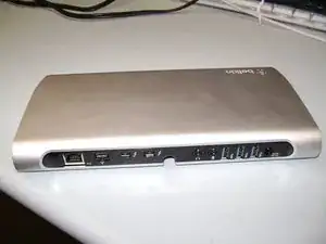
The only tools needed are a philips screwdriver and a narrow putty knife.
Werkzeuge
-
-
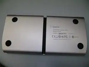
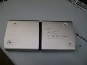
Use a putty knife to remove the four rubber feet. Once removed, there are 4 phillips screws to be removed.
-
-
-
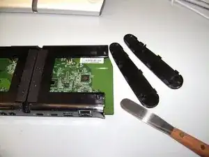
The next step is to use the putty knife to pry off one of the two plastic endcaps, they snap out and the circuit board slides out.
-
-
-
Use the phillips screwdriver to remove 5 more screws to remove the plastic mounting frame.
-
-
-
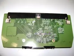
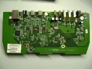
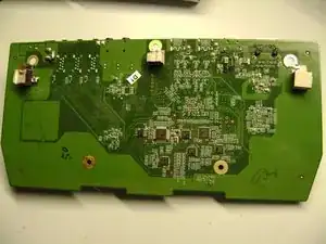
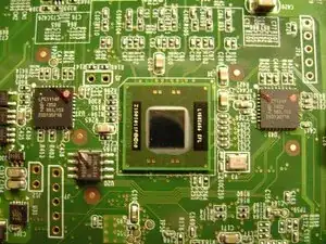
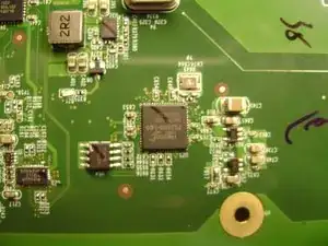
Front and back of the board.
-
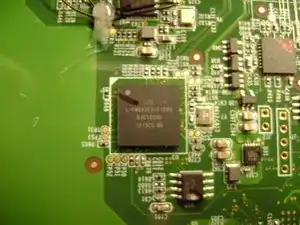
From left to right on the front of the board the major chips are: LSI FW643E-02 (FIreWire800); Broadcom BCM57762 (gige); Intel L150I56 (Thunderbolt controller), NXP LPC1114F (two), Fresco FL1100 (USB3); C-Media CM119A (Audio)
-
From left to right on the back of the board the major chips are: Parade PS161HDM; Parade PS8301 (two); NXP ZSD310 (two); Parade PS8321. The chips seem to support HDMI/DVI conversion and Display Port!
-
2 Kommentare
Hi… someone have the board scheme, please?
My express dock only flashing the Led when I plugged the power cord and turn off
I cannot get any power going into the dock. I was wondering if anyone has had any experience with the analog board and dead power. The cables are hot so I know it must be the dock itself. Just nothing. Its internal leds do not light up and the Ethernet port has no activity lights either.
Any advice would be welcome.
airira -
