Einleitung

  1. WYGgewMEYYvA2gGa
    WYGgewMEYYvA2gGa
    yywmltxGONYROWRi
    n1RQBfPBnGE61l4F
    • Only trained and qualified personnel should be allowed to install, replace, or service this equipment!

    • During this procedure, wear grounding wrist straps to avoid ESD damage to the card. Do not directly touch the backplane with your hand or any metal tool, or you could shock yourself!

    • Make sure that the power switch is turned to standby and that the power supply cable is disconnected. Disconnect all cables from the router back panel.

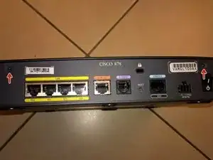
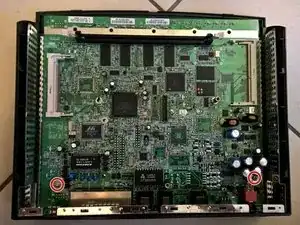
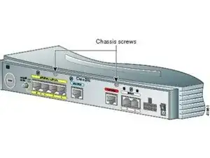
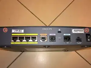
    • Use the Phillips #1 Screwdriver to remove the two screws on back side of the device.

  2. 4sZGq1EJHJopBINF
    4sZGq1EJHJopBINF
    XPRQLN4MlFTGBZ2H
    BxMugnfK1mIMD1xd
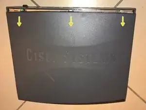
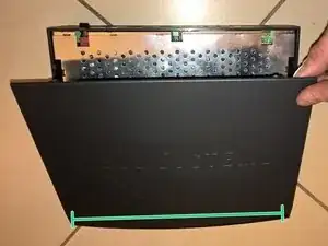
    • 1. Gently push the top cover of the router away from you.

    • 2. Lift it up top cover from the bottom of the router.

    • 3. Remove top cover from the device.

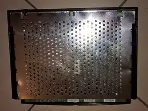
    • Place the router bottom on an antistatic mat.

  3. mn6Z54vWyj3a5AaL
    mn6Z54vWyj3a5AaL
    DKk4q2CXRFOUT1tU
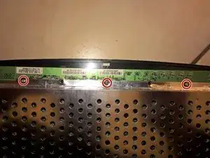
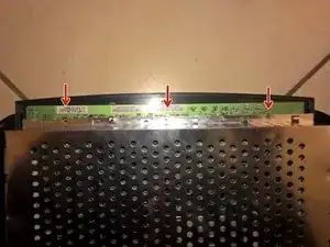
    • Use the Phillips #1 Screwdriver to remove the three screws on front side of the device.

  4. HI4JxVsp3frsWHP1
    HI4JxVsp3frsWHP1
    uaJVthwPQxdmrn54
    cIXFqR3HAbPVCGFU
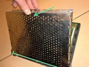
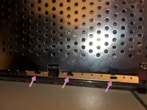
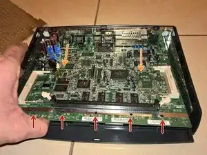
    • 1. Gently lift up inner metal shield from the bottom of the router.

    • 2. Remove inner metal shield from the device (see the anchors on the picture).

    • Be careful and do not distort the plates!

  5. ca2eOEtc1fCVAlUL
    ca2eOEtc1fCVAlUL
    LEACxAOSIZZaRInt
    2spoEScQIgTXjDWF
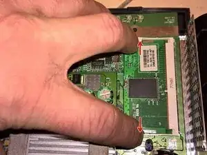
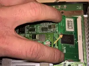
    • 1. Place your fingers on the levers at the two sides of the slot, and push open.

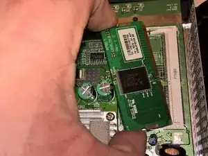
    • 2. Firmly pull the release lever away from the module until the module pops up.

    • 3. You can then remove the module from the module slot.

  6. pZ5EUTF32YIrwrWy
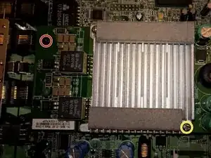
    • 1. Use the Phillips #1 Screwdriver to remove the black screw.

    • 2. Use the Phillips #1 Screwdriver to remove the silver screw as shown on picture.

    • You should remove just only one silver screw - the second one is holding just cooling plate.

  7. yaGoXuX3nwYQZAIn
    yaGoXuX3nwYQZAIn
    LuIWSnAKZatIE5WD
    ABHTLKSGrO3VD3RB
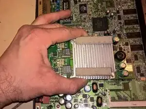
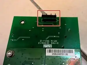
    • Gently pull the module up to disconnect two connectors underneath.

    • Be careful and don't damage 4-pin connector (marked RED).

  8. 5PuA2FNvIfCI3wD5
    • Use the Phillips #1 Screwdriver to remove the two screws holding the motherboard.

    • When putting screws back, don't use force - threads are made of plastic!

  9. iTxYMd3sYghdnk13
    iTxYMd3sYghdnk13
    epp1HTXtaHMt5gM2
    tgALKmGq1rplxyhM
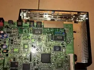
    • 1. Gently lift up the board to release plastic locks.

    • 2. Gently pull the board away from backside panel (to release metal shielding locks around connectors).

    • 3. Remove board from the case.

  10. GPCxOFNx3h3IZNxr
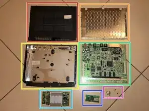
    • Parts and pieces:

    • Top cover

    • Inner metal shield cover

    • Bottom part of case with metal shielding

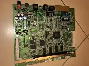
    • Motherboard

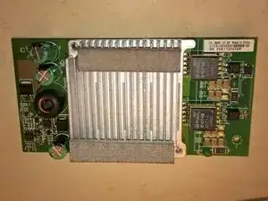
    • SHDSL Filter Module board

    • StrataFlash Memory Module

    • 1 black screw, 1 silver long screw (1 is still on SHDSL Filter Module board), 7 silver screws

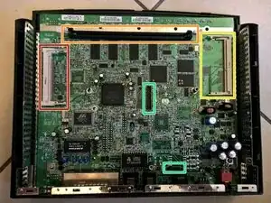
  11. AZgjGxwOxXYq1iJS
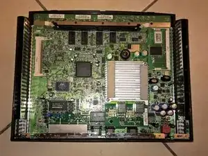
    • mini-PCI slot for WLAN card

    • DRAM socket for additional RAM Memory Module

    • Slot for additional StrataFlash Memory Module (4MB module installed)

    • Two connectors for SHDSL Filter Module board

Jiri Altman

Mitglied seit: 04/05/16

1479 Reputation

3 Kommentare

Sorry mate, that's not a CPU board but a SHDSL line filter. CPU is the biggest, center chip (freescale)

karmansan -

Thx for info! I will update my guide accordingly...

Jiri Altman -

is it possible to add wireless capability to this router by installing a wifi card in the empty mini PCI slot?
timber poodle -