Einleitung
Werkzeuge
-
-
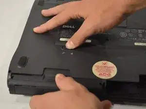
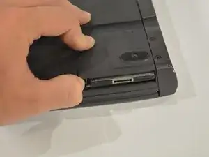
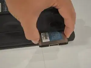
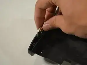
To start, you need to remove the CD or Floppy Drive, whichever is installed, and the battery. They remove the same way. Push left on the tab and pull out on the drives to remove them. My battery has gone MIA at the moment, but it removes the same way.
-
-
-
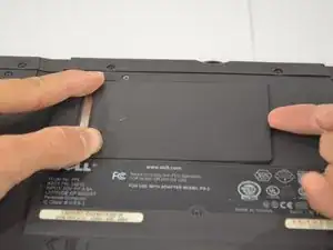
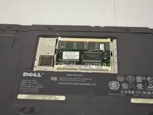
Slide off the RAM cover by lifting up on the right side and sliding it to the right. Then push out on the tabs on the side of the RAM till they pop up, then you can pull them out.
-
-
-
Push on the button next to the slot your card is in till and it will pop out. Push in on it again to pop out the actual card.
-
-
-
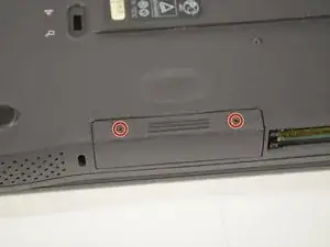
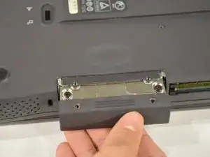
Unscrew the two screws holding in the hard drive caddy, and slide out the hard drive.
-
Two 5mm Screws
-
-
-
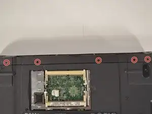
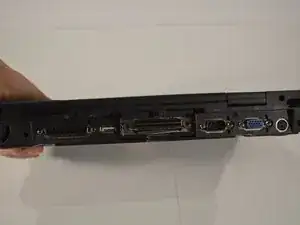
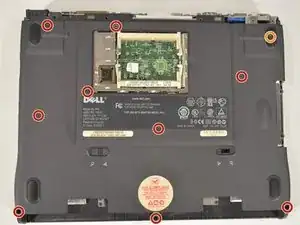
Unscrew the five screws along the bottom of the laptop, then remove another seven screws along the back of the laptop, then simply pull off the IO cover.
-
Five 5mm Screws
-
-
-
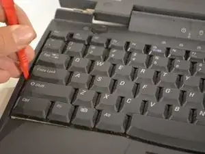
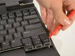
Use a plastic pry tool or a small flat-head screw driver to gently pry up on the left side of the keyboard until it pops up. Do the same for the right side, and slowly lift up the keyboard.
-
-
-
Use a plastic pry too of a small flat-head screwdriver to VERY gently pry on the keyboard cable connector on it pops off.
-
-
-
Use the screwdriver you've been using and gently put it under the ribbon cable and pull up until it pops out.
-
-
-
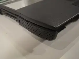
There is one screw to remove that is holding on the palm rest. Pop up both sides of the palm rest. They may be very tough to pull off, but they shouldn't break.
-
One 5mm Screw
-
-
-
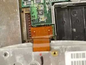
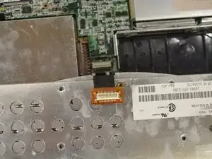
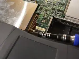
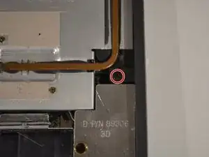
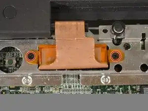
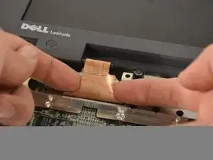
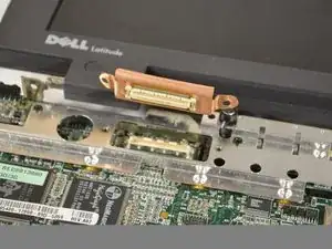
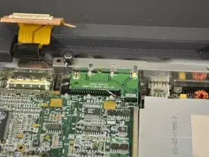
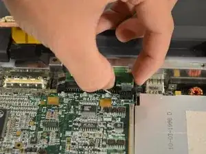
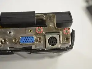
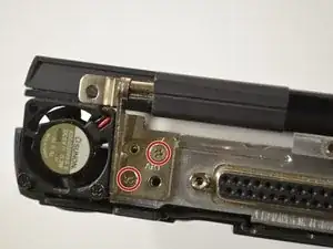
Remove both grounding screws on either side of the ribbon cable. Gently pull up on the ribbon cable with your fingers until the cable pops off.
-
Two 5mm Screws
-
-
-
Remove the four screws holding the IO shield, and pull up and to the right to remove it.
-
Four 5mm Screws
-
-
-
Remove the screw holding it on and pull up on the IR blaster till it disconnects.
-
One 5mm Screw
-
-
-
Remove the screw holding the audio board cover, then pull off the cover. Remove all three cables connected to board by gently pulling on them with your finger nails. Simply pop off the audio board then pull it out to the left.
-
One 5mm Screw
-
-
-
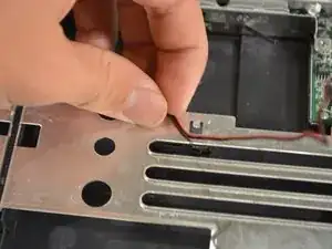
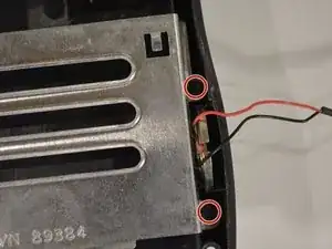
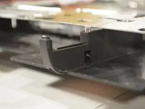
Remove the speaker wire from bottom bracket holdings and bend it out of the way to remove the bottom case bracket.
-
-
-
There are two screws on either side of the bracket to remove. You need use a small screwdriver to push up on a plastic clip on the middle of the bracket.
-
Four 5mm Screws
-
-
-
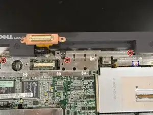
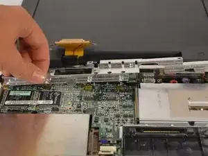
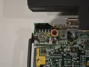
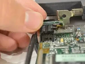
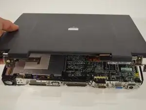
There are two screws on each hinge, remove them and take off the whole LCD assembly.
-
Four 5mm screws
-
-
-
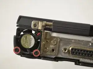
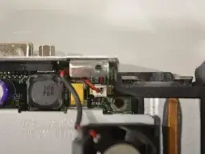
Remove the two screws holding the fan in, and disconnect the fan connector using your fingernails.
-
Two 12mm Screws
-
-
-
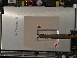
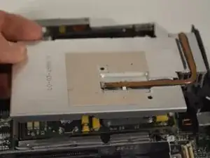
Remove the two screws holding in the thermal cooling assembly, and lift it out, along with the plastic air flow duct that is around the heat sink.
-
Two 2.5mm Screws
-
-
-
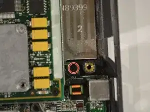
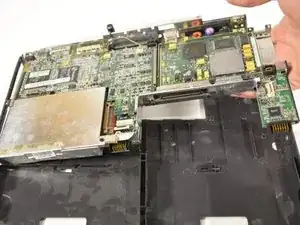
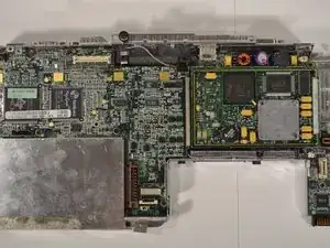
There is one screw to remove, then you can lift out the entire board by lifting up on the right side, and pulling out to the right.
-
One 5mm Screw
-
