Einleitung
Werkzeuge
-
-
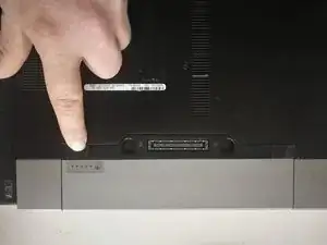
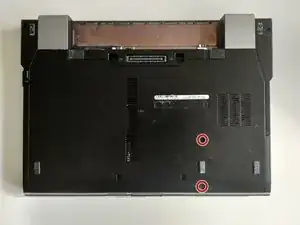
Disconnect AC power adapter.
-
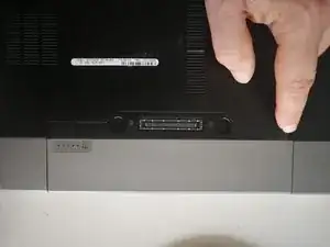
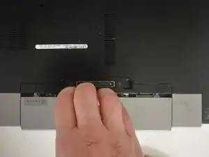
Push battery release tabs inwards, and slide the battery out of the computer.
-
-
-
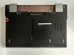
Remove the two 2.8mm Phillips screws securing the hard drive.
-
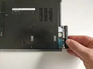
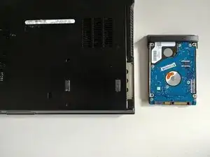
Pull the hard drive out of the laptop.
-
-
-
Remove the 2.8mm Phillips screw securing the optical drive removal button.
-
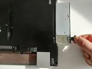
Press the removal button on the side of optical drive.
-
Pull the Optical Drive out of the laptop.
-
-
-
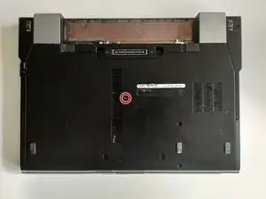
Remove the one 7.5 mm Phillips screw securing the bottom case.
-
Pull the bottom lid towards yourself to remove it.
-
-
-
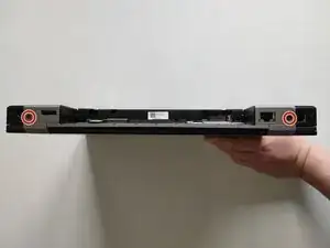
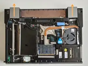
Remove the two 4.8mm Phillips screws securing the plastic lids.
-
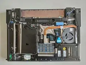
Slide the plastic lids of the case.
-
-
-
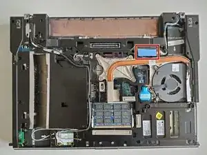
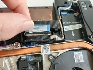
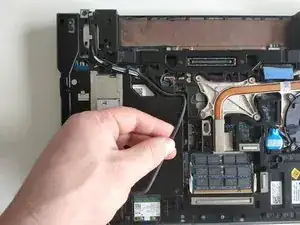
Grab the plastic pull tab secured to the display data cable lock and pull the display data cable connector straight up from its socket.
-
De-route the display data cable from the channel.
-
-
-
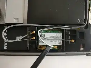
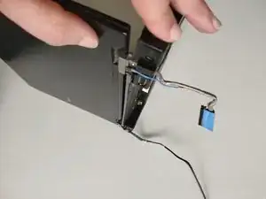
Using spudger lift and disconnect Wi-Fi antenna cable.
-
De-route the Wi-Fi antenna cable from the channel.
-
-
-
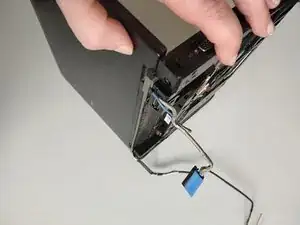
Open your laptop so the display is perpendicular to the upper case.
-
Place your opened laptop on a table as pictured.
-
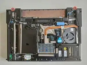
While holding the display and upper case together with your left hand, remove the two 4.8 mm Phillips screws from the display brackets.
-
Grab the upper case with your right hand and rotate the display slightly away from the upper case. Lift the display away from the upper case, minding any brackets or cables that may get caught.
-
-
-
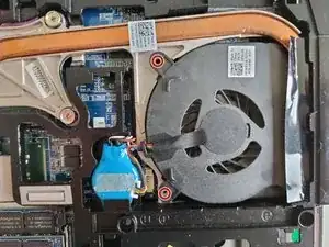
Remove the two 4.8mm Phillips screws securing the fan.
-
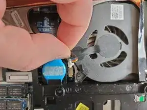
Disconnect the fan by pulling power cable straight up.
-
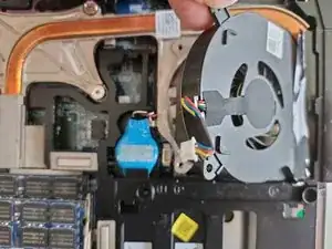
Lift the fan with your finger and slide it out towards the inside of the laptop.
-
-
-
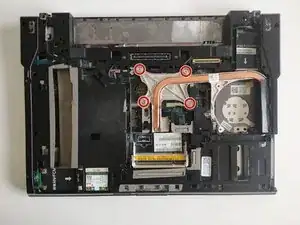
Remove the four Phillips screws securing the heat sink.
-
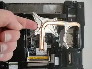
Using your finger gently lift and remove heat sink .
-
-
-
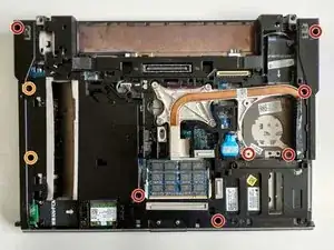
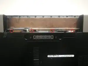
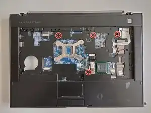
Remove the seven 4.8 mm Phillips screws securing the upper case.
-
Remove the two 4.8 mm Phillips screws securing the upper case.
-
-
-
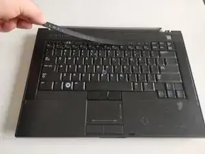
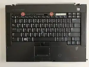
Remove the two Phillips screws holding the keyboard
-
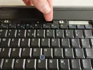
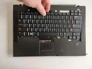
Holding the plastic film gently lift the keyboard upwards to realise the side clips.
-
Pull the keyboard towards the screen to slide it out from the sockets.
-
-
-
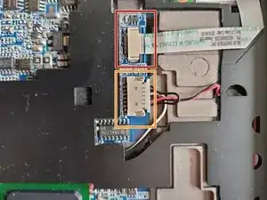
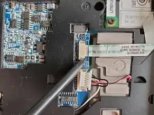
Use the tip of a spudger to slide out the locking lever to release the Wi-Fi switch ribbon cable from its socket.
-
Pull the Wi-Fi switch ribbon cable straight away from the logic board.
-
Disconnect the speakers cable by pulling the male end straight away from its socket.
-
-
-
Disconnect the keyboard and touchpad cable by holding plastic film and pulling the male end straight away from its socket.
-
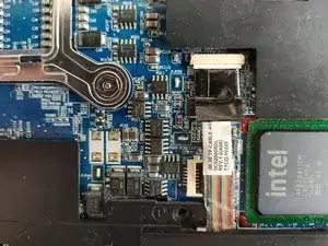
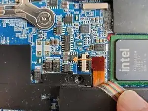
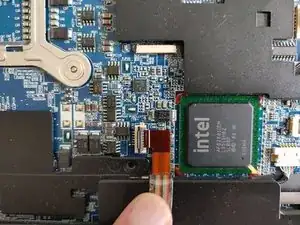
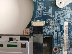
Use the tip of a spudger to flip up the locking lever to release the contactless smart-card reader ribbon cable from its socket.
-
Pull the contactless smart-card reader ribbon cable straight away from the logic board.
-
-
-
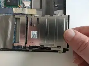
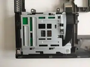
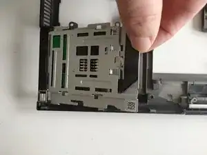
Remove the two 2.8mm Phillips screws securing the PC Card slot.
-
Gently lift the PC Card slot and slide out of the socket .
-
-
-
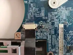
Use the tip of a spudger to flip up the locking lever to release the smart-card reader ribbon cable from its socket.
-
Pull the smart-card reade ribbon cable straight out of its socket.
-
-
-
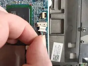
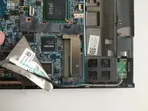
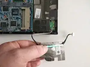
Disconnect the IEEE 1394a connector cable by pulling the male end straight away from its socket.
-
De-route the IEEE 1394a connector cable from the channel.
-
-
-
Turn the laptop upside down.
-
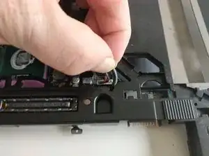
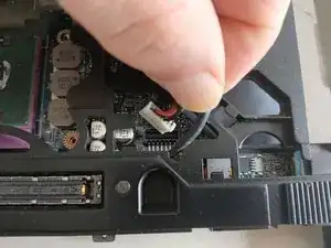
Disconnect the AC adapter by pulling power cable straight up.
-
-
-
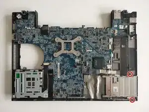
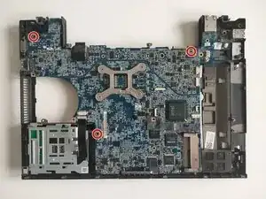
Remove the four 4.8mm Phillips screws securing the logic board.
-
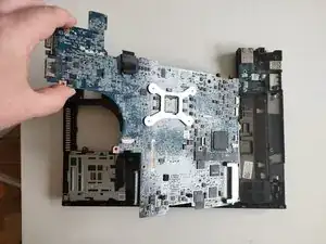
Gently lift the logic board out of the bottom bottom case.
-
-
-
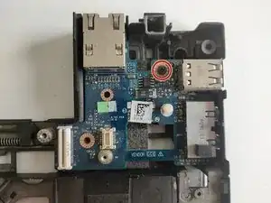
Remove the 4.8mm Phillips screw securing the I/O board.
-
Lift the I/O board out of the bottom case.
-
