Einleitung
Remember to set up a proper ample place to work with, as well as a plan to layout the screws so that you don't loose any.
Take precautions for ESD by wearing an ESD wristband and hooking it up to a grounded metal.
Specs of this Dell Latitude E6500:
CPU: Intel Core 2 Duo T9600 2.8 ghz 1066mhz fsb
Ram: 2x2GB DDR2 PC26400 800mhz ram
GPU: Nvidia Quadro NVS 160M 256mb DDR3
HDD: *upgrade* Intel X25-M G2 80GB SSD
Display: 15.4" 1920x1200 AG coating LCD
Backlit Keyboard, PC Card/Express Card/SD card/Smart Card (contactless/physical).
Werkzeuge
-
-
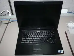
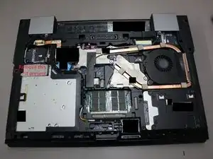
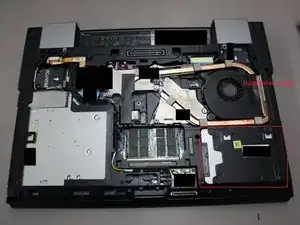
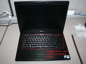
The layout of the Dell E6500.
-
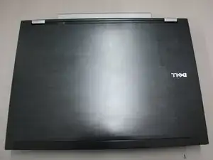
Closed lid, and open lid shots.
-
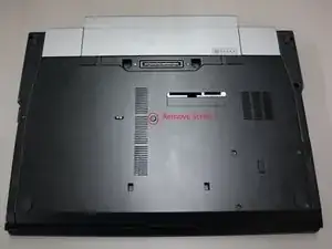
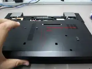
Remove the battery and press the power button for 10 seconds to discharge capacitors prior to opening the laptop.
-
-
-
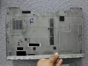
Remove Service hatch:
-
Remove one captive screw using a #1 Philips Screwdriver.
-
After the screw is removed, proceed to remove the hatch by pushing outwards towards you then lifting the hatch and removing it.
-
-
-
Remove E-Modular DVD Bay
-
Remove screw if present by using a #0 Philips Screwdriver. Typically it is not and the DVD bay is held in place by the latch system used in many Dells.
-
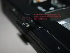
Press the latch, inwards inside the laptop until you hear a latch click sound. Release it and the latch should pop out.
-
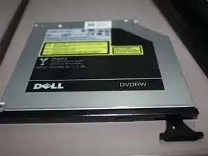
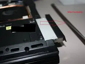
Remove the drive by pulling on the latch.
-
-
-
Remove Hard drive assembly.
-
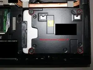
Locate Hard Drive assembly on the lower right hand corner.
-
Remove four screws using a #0 Philips screw driver.
-
Remove the hard drive assembly by pulling it out using the plastic caddy.
-
-
-
Remove hard drive from hard drive caddy.
-
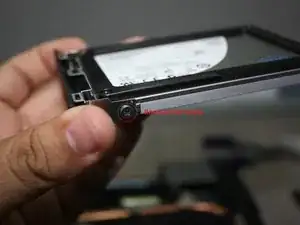
Remove one screw using a #0 Philips Screw driver. The other side will not use a screw but a lock on metal slot.
-
Remove the hard drive by sliding the side that previously held the screw, then pushing to the opposite side where the lock is.
-
-
-
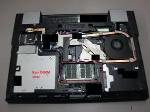
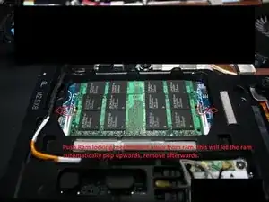
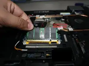
Removing RAM modules from the 2x DIMM slots.
-
Look for the ram module bay. It will be found on the lower half of the notebook in the middle.
-
Release the two locking mechanisms on the side. The ram will automatically move upwards.
-
Firmly hold both sides of the ram modules, and pull it outwards gently.
-
-
-
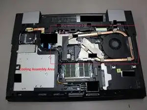
Remove Cooling Assembly Part 1 of 2.
-
Locate cooling assembly found on the middle top part of the notebook stretching towards the end of the right side.
-
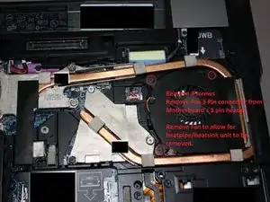
Remove Heatsink fan by removing three screws using a #0 Philips Screwdriver.
-
Disconnect 3 pin fan connector from the 3 pin motherboard header.
-
-
-
Remove Cooling Assembly Part 2 of 2.
-
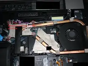
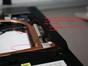
Loosen 4 screws on the CPU heatpipe/heatsink assembly using a #0 Philips Screwdriver in order of 1-2-3-4.
-
It is important to follow this order to ensure the most even pressure thus reducing the risk of damaging the CPU core, and its socket.
-
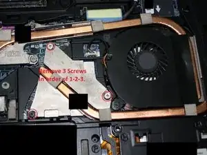
Loosen 3 screws on the GPU heatpipe/heatsink assembly using a #0 Philips Screwdriver in order of 1-2-3.
-
It is important to follow the order to prevent uneven pressure on the GPU, and prevent damage to the pins.
-
-
-
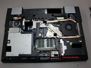
Remove wireless card/antennas.
-
Locate wireless bay on the bottom near the middle.
-
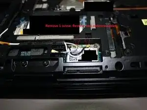
Remove 1 screw with a #0 Philips Screwdriver.
-
Remove the Black, White, and if applicable the grey antenna cables. You remove then by "popping" them out of the wireless card. A flat head screw driver can be useful for very tight fit.
-
-
-
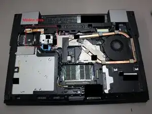
Removing Modem card if applicable.
-
Locate Modem bay on the middle left of the laptop next to the cooling assembly.
-
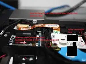
Disconnect the ribbon cable by unlocking the two side pressure pins, then pulling the ribbon cable free little force is necessary.
-
Remove 1 screw using a #0 Philip Screwerdriver.
-
Pull the modem card out but be careful because there is another cable underneath it.
-
Remove the 2 pin cable from underneath from the 2 pin header found on the modem card's PCB.
-
-
-
Removing the hinge covers, and separating the LCD assembly from the assembly. Part 1 of 2.
-
Locate all antenna cables, and display cables associated from with the LCD assembly.
-
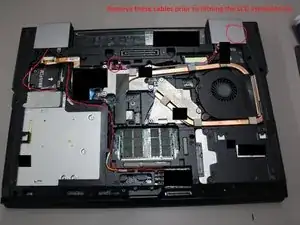
Disconnect all antenna cables, and display cables and loosen them from their routing holders found on the assembly. One antenna is found on the top right corner below the right hinge cover.
-
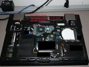
Remove four screws using a #0 Philips Screwdriver. Two are found in the picture, another two are found on the back.
-
Remove the hinge covers by pushing outwards away from the laptop. Lift and remove.
-
With the hinge covers removed, you will see two screws, one for each of the hinges. Remove these screws with a #0 Philips Screwdriver.
-
-
-
Removing the hinge covers, and separating the LCD assembly from the assembly. Part 2 of 2.
-
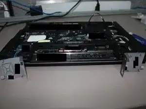
Flip the notebook over. Open the LCD carefully with firm downwards pressure.
-
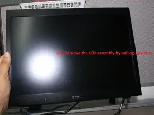
Remove the assembly by pulling upwards. There should be very little to no resistance.
-
Remember to be careful with any cables still held in place that you may have forgotten.
-
-
-
Removing Backlit Keyboard. Part 1 of 2.
-
Stand the laptop upwards, and lift the screen upwards to show the keyboard.
-
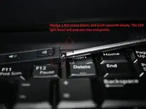
Locate the small LED indicator panel found on top of the keyboard. Use a small flat head screw drive, and dislodge it. It requires minimal force. Remove the LED indicator bezel.
-
-
-
Removing Backlit Keyboard. Part 2 of 2.
-
Remove two screws on the side of the keyboard using a #0 Philips Screwdriver.
-
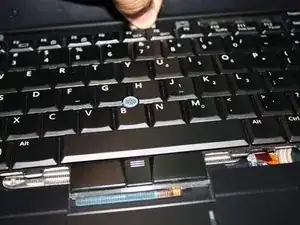
Use the black film found in on the top middle part of the keyboard. Pop the top part of the keyboard out a bit and pull with the film. It will unlock the keyboard.
-
-
-
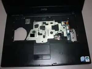
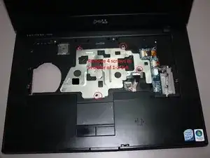
Removing metal faceplate found underneath keyboard, providing less keyboard flex as well as protecting the motherboard from strong keystrokes.
-
Remove keyboard. (see step #13-14.
-
Remove 4 screws in order from 1-2-3-4 using a #0 Philips Screwdriver.
-
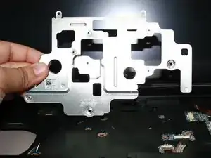
Lift the metal faceplate.
-
Enjoy the view.
-
-
-
Removing Top Palm rest from bottom assembly. Part 1 of 2.
-
Follow steps #2-#15 to remove all components.
-
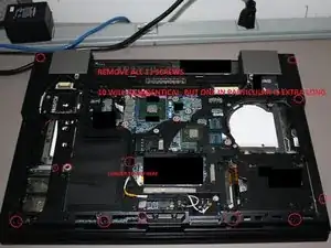
Turn the notebook on it's back. Remove 10 screws+1 extra long screw using a #0 Philips Screwdriver.
-
One screw on the right side, near where the Optical disc bay is may not come out that is okay.
-
Turn notebook over on so it rests with the palm assembly upwards.
-
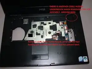
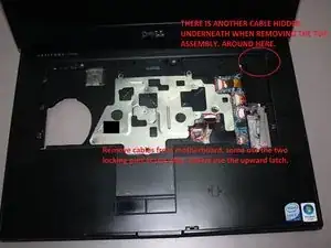
Remove one screw, and disconnect all cables. Keep in mind when you remove the palm rest assembly there will be a hidden cable as mentioned in the picture.
-
Remove 1 screw labled "2 >" using a #0 Philips Screwdriver.
-
-
-
Removing Top Palm rest from bottom assembly. Part 2 of 2.
-
Once all 12 screws (11 on bottom, and 1 on top) are removed it is time to remove the assembly.
-
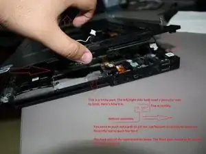
Be careful when removing the assembly, use the picture to get an idea of how to remove it.
-
The top portions of the assembly is loose and be moved. The right/left side use a locking mechanism as detailed in the picture to help you remove it. The bottom part needs to be pushed inwards to unlock and finally remove the assembly.
-
NOTICE THE 4 PIN (or 3) CABLE IN THE PICTURE IT NEEDS TO BE DISCONNECTED FROM THE 4 PIN HEADER (or 3).
-
Enjoy the view. ;)
-
-
-
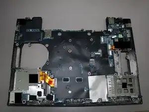
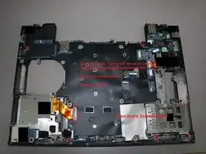
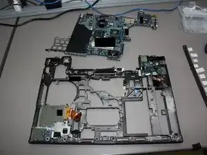
Removing motherboard from bottom assembly. I show a picture of the top palm assembly for precaution again.
-
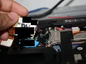
Disconnect the two ribbon cables found on opposite corners of the motherboard.
-
The cable on the bottom left should have two pressure pins, if not just pull the cable out.
-
The cable on the top right will have two pressure pins for locking, release them and pull the cable out using the hard film.
-
Remove 8 screws from the motherboard using the #0 Philips Screwdriver.
-
4 black screws are found along the edges of the motherboard.
-
2 Metalic screws are found underneath the ribbon cable on the bottom left. Remove them. The last 2 screws are on the hard drive cage on the bottom right.
-
Enjoy the sight. You are done! There are a few other parts but those should be easy to remove from here.
-
7 Kommentare
Thanks for this excellent guide. I used it yesterday when my mouse key was getting stuck. I popped open the Dell and had removed most everything in order to get to the keyboard and mouse when I noticed the mouse wasn't stuck anymore, so something in the process had dislodged it and I went about re-assembly. The sequencing of what to remove in what order is very helpful.
Daniel -
Do you know the size of the screws being used on this Dell Laptop? Specifically the Lid Hinge Screws (2 on each hinge). I have an E6510 that's missing those screws, apparently someone has been in this before.
brad -
If you mean the 2 screws on each side under the hinge covers holding the LCD assembly to the chassis, those are going to be M2.5x8 screws (same ones used for the "P" labeled screws.
It's the same size if you are talking about the hinge screws inside the LCD assembly (behind the bezel).
Thanks for making VERY helpful guide! My Dell Latitude E6500 went into 'black screen' and would not boot after I accidently leaned my elbow too hard to the left of the touchpad. Disassembling the E6500 revealed inductor PL17 burnt (PL17 is located just underneath where I placed my elbow). It was impossible for me to measure the inductance, because PL17 was split in two halves. PL17 was black, and package size 0603. Since the tracks around PL17 is around 4mm wide, I assumed possibility for higher current. Therefore I selected the lowest inductance value of 'black' inductors in the 0805 series which is 82 nH (measured serial resistance to be between 50 and 60 mohm). I doubt the selected value is the correct one, but I think it is worth a try. Replaced inductor, reassembled the PC, powered up, and it works like a charm as nothing had happened!!! To prevent short circuit to happen again, I isolated all components in this area with a layer of kapton tape. Thanks again for making such good disassembly instruction.
gpetters -
