Einleitung
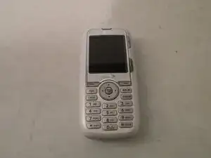
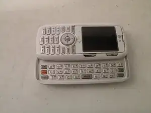
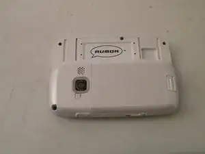
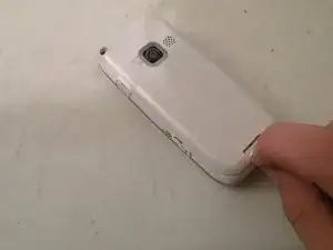
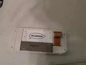
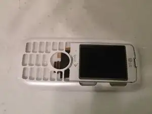
The LG Rumor is a full QWERTY keyboard slider phone available from Sprint in 2008. It has an SD card slot and runs a unique OS.
Werkzeuge
-
-
The LG Rumor, This phone is the broken phone that I can't seem to fix also depicted here: Turns on, then shuts off right after
-
-
-
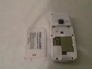
Now, start by removing the battery, it is attatched to the back cover, and can be removed by pushing the tab back.
-
-
-
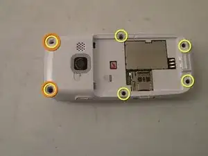
Remove these 6 phillips screws:
-
These two top screws are covered by rubber plugs that can be removed by a small flathead screwdrivew, or a fingernail.
-
-
-
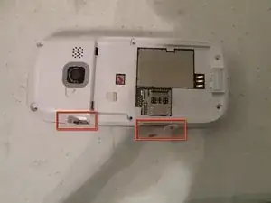
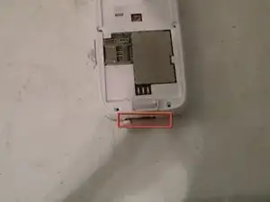
Remove the covers for the Headphone, Micro SD and Charging connectors, but be careful, they are still connected, pull them only as far as they will come out!
-
-
-
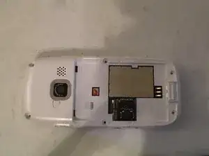
You should now be able to lift the back cover off, it is held on with a mild adhesive, so a little force may be required the first time.
-
-
-
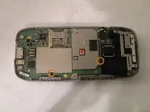
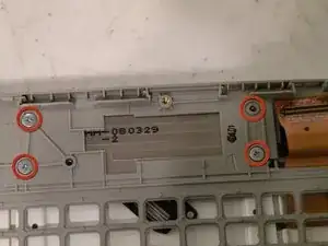
Remove these two phillips screws:
-
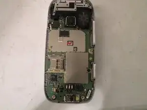
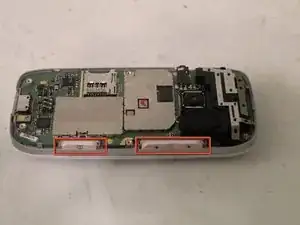
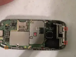
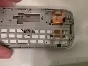
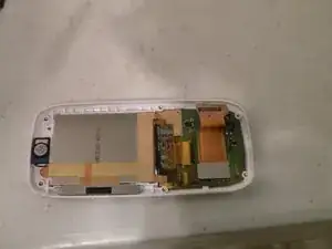
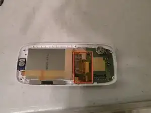
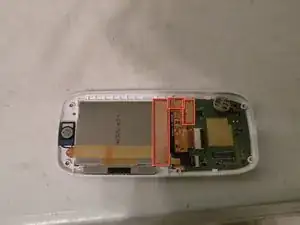
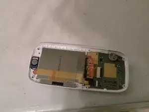
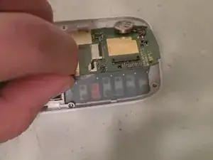
Now, removed the highlighted clips (2nd Picture) this will free the logic board.
-
I recomend starting with this one, and once this tab is free, you can just slide it around the other clips.
-
-
-
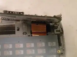
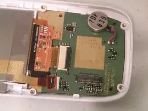
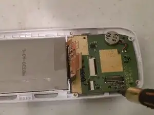
Now, pivot the logic board up, to reveal the LCD/Numeric Keypad Cable, remove this with a spudger or flathead screwdriver.
-
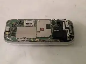
You should now be able to remove the logic board.
-
-
-
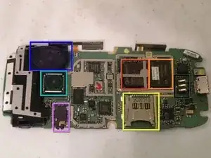
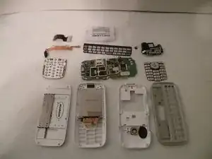
The Logic board:
-
The CPU is a Qualcomm MSM6100 ARM Processor
-
The RAM, it is manufactured by Hynix
-
The Camera 1.3MP, not bad
-
The SD Card Slot:
-
Speaker [Speakerphone]
-
Headphone Jack:
-
Battery Contacts:
-
-
-
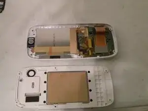
Seperating the phone sliding assembly:
-
Remove these 4 Phillips screws:
-
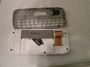
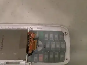
Now, lift it off, threading the Screen/Number Pad Cable Through the hole.
-
-
-
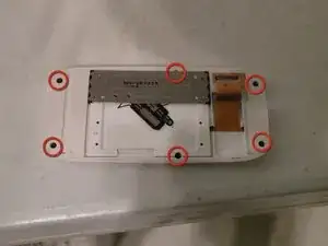
Remove these phillips screws:
-
Now, using a spudger, or flathead screwdriver, seperate the two halves of the assembly, threading the data cable through it's hole.
-
-
-
Now, detatch the data cable from the board using a spudger, be careful, it is a fragile connector, and you should lift it straight up.
-
Now, remove this piece of clear yellow-tinted tape covering the connectors.
-
-
-
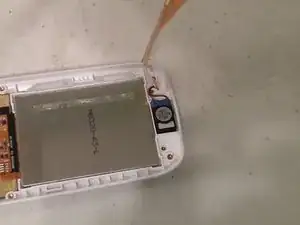
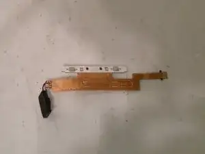
Now, flip this tab up, towards the bottom of the phone, and remove the speaker/side-button cable.
-
Now, slowly lift the cable up, minding the adhesive on the back.
-
When you come to the buttons, be especially careful, and when you get to the speaker, use a flathead screwdriver, and pop the speaker out.
-
-
-
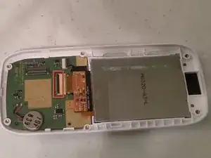
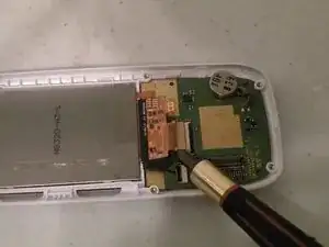
Using a spudger or flathead screwdriver, lift this tab up, to release the display cable.
-
Now, guide the cable out of the connector, until you can set it on top of the assembly.
-
-
-
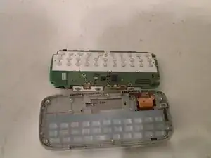
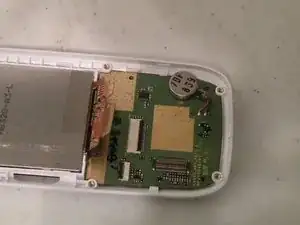
Now, to remove the board, use a flathead screwdriver or spudger to clear the tab on one side, then remove the board completly, similarly to the logic board.
-
-
-
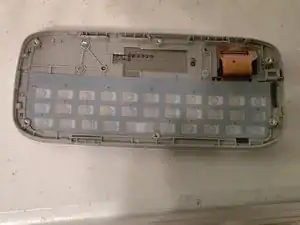
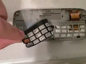
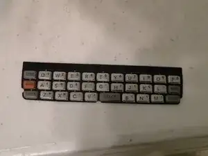
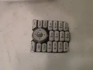
You can now lift the keypad cover off, just like we did earlier with the alphabetical keyboard.
-
-
-
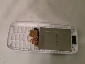
Unfortionatly, the LCD panel is held in place by a heavy adhesive, and removal will almost certianly crack the screen, so only remove it if you are replacing the screen.
-
2 Kommentare
I'd recommend not opening the screen bit in any way shap or form.
I tore down an AX260. Tear down is identical. I removed the screen, too. I heated the entire glass with a variable heat gun set to approximately 140F. I monitored the temperature of the glass with a non contact infrared thermometer. At just under 140F the screen separated from the glass on three sides. I hinged the screen and applied the heat to the remaining adhesive. As it warmed the adhesive disengaged from the screen intact. The adhesive acts like a sticky foam. Screen was clean with no adhesive residue and would be easy replace glass or screen at that point.
Thank you for a very nice tear down guide.
jharden2 -
