Einleitung

  1. fliTAROwLBZ6CqFp
    fliTAROwLBZ6CqFp
    4KLK3D3XyK3xylUU
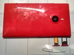
    • Remove the SIM card and micro SD trays using a paperclip or SIM card remover to eject the trays.

  2. rRsfiObyoSaKYUOq
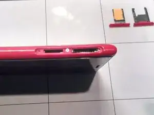
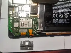
    • The plastic frame is locked to the internals by a single screw located between the SIM and micro SD slots.

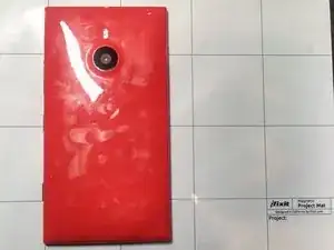
    • Remove the QR code sticker to reveal the screw.

    • Unscrew using a 0.7mm Hex screwdriver

    Screw is actually P2, not 0.7 Hex

    Lee Edgett -

  3. CMRWCXpehG3aIWUU
    CMRWCXpehG3aIWUU
    EiCFoZKMgFqNbdnd
    JUTlcIEbP2PAbMlw
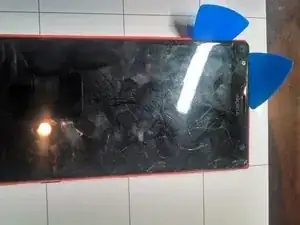
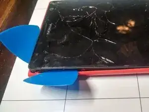
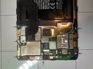
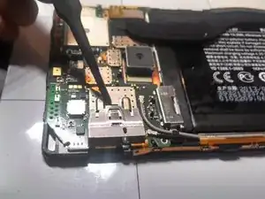
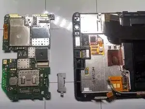
    • Using plastic picks, begin to separate the frame from the internals at the corner of the phone containing the SIM tray.

    • Work around the top of the device placing more picks between the frame and the internals.

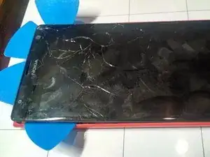
    • Once the top is removed from the Plastic frame work down the sides and remove the plastic frame.

  4. V6UixQR5rX3hDFFq
    V6UixQR5rX3hDFFq
    PFRExDrdBRIs2OrK
    ndnGOU5cZBPSKSoi
    • With the frame removed we can get a look at the internals.

  5. fYSPJnHQ1VmI1WTy
    • Remove the six T4 screws indicated in the image.

  6. KhgpPO11HosRGh5g
    KhgpPO11HosRGh5g
    KEKQOkvGuFKX6pMC
    • LIft up and remove the metal strap that covers the pop connector on the board.

  7. h4jN2OMNUMdy2woh
    h4jN2OMNUMdy2woh
    JnIOhGhtTuPPaKsk
    • Slide away the other metal strap that covers more pop connectors.

  8. 6kMtvegV4AvcoATw
    • Gently lift up on the four pop connectors to demate and remove them from the board.

  9. iMBYnTia43pTGVeA
    • Remove the two coaxial cables by gently lifting up.

  10. hxPDPhhRETFx5BJi
    hxPDPhhRETFx5BJi
    v4vhgUEUMDBUB6bG
    • The motherboard can now be lifted from the unit.

  11. nvJYmQqrcQn66L4e
    nvJYmQqrcQn66L4e
    DcYBtGxdZvZKqQUr
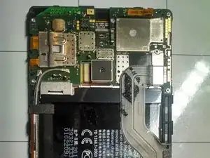
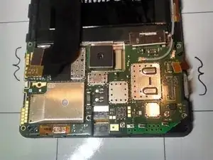
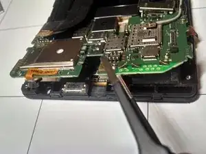
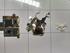
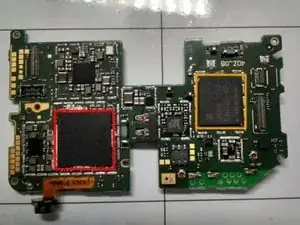
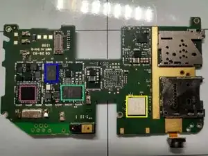
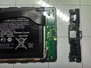
    • The board level shielding was soldered to the board and required prying and breaking to reveal the chips.

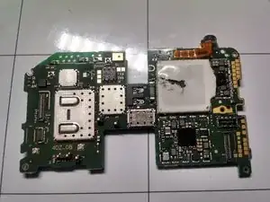
    • Once the board level shielding was removed, the silicone thermally conductive rubber was scraped away from the processor.

    I don't understand why this step was performed.

    Wade -

    If you're trying to get to the screen, or another part of the phone I don't think it's a necessary step. I think it was done just to show a full phone teardown.

    Zack -

    Zack is right, this step is just to view and identify the ICs and parts on the motherboard. Do not perform this step if you wish for you phone to remain functional.

    alcs99 -

    Just had my little Nokia Lumia 1520 unlocked at http://www.attphoneunlockingshop.us/ Thanks !!!. this is the only site i use to unlock lumias:

    https://www.youtube.com/watch?v=uu4q4rEy...

    Allen -

    Would you consider adding a section for separating the glass from the rest of the unit?

    Kevin -

  12. VHih4vOydRShpvhv
    VHih4vOydRShpvhv
    QLhMxO2tSirklk3f
    • Samsung KLMAG2GEAC-B001 HMHB656EU 337

    • Samsung K3QF2F2ODM OGCE 6F63209X 337

    • 405707 D925A4

    • RF7459A F14L10Y

    • SWH GMF81

    • WTR1605L OVV PPV438Z2 AB31801 10

  13. gbE4IvVURNlRIlV2
    gbE4IvVURNlRIlV2
    j4dlCmXpZCC4qpn3
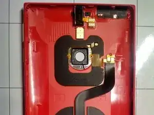
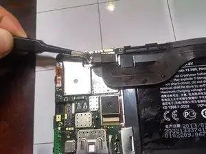
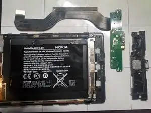
    • The antenna module is adhered to a daughter board with a soft sticky adhesive.

    • Remove the Antenna module by removing four T4 screws.

  14. WQD3FhFTXrnVCyQ5
    WQD3FhFTXrnVCyQ5
    qvpyxNHZ3TJvjFVc
    JrLO2Ra65POYYpMX
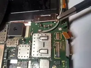
    • Remove the coaxial antenna cables by gently prying them up.

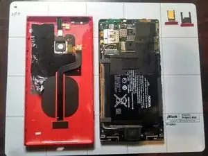
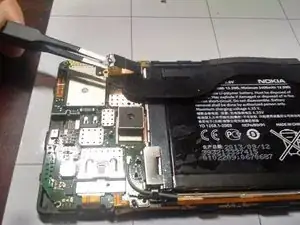
    • The Daughterboard and flex cable come out of the phone easily.

    • At this point we can see the USB connector is soldered to the board making replacement of this component expensive.

    This is also the microphone.

    richstrapple -

    The microphone is on the pcb located directly above to the usb connector (in the corresponding picture). It looks like a small rectangular piece of brass. It is actually quite common for the microphone on this particular Lumia to be turn up defective or not keep its connection, via the ribbon cable, firmly with the motherboard.

    Rob Wisdom -

  15. ZT36hVm1fwqaHRDR
    ZT36hVm1fwqaHRDR
    HfZI21KIQE1cWsja
    jIjFAeQhoCsrwdTJ
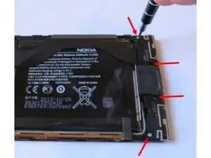
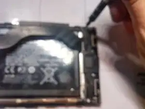
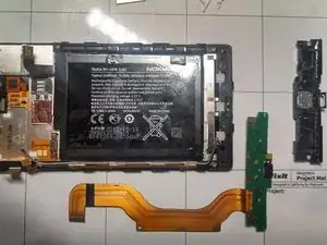
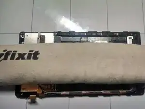
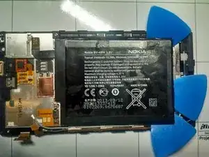
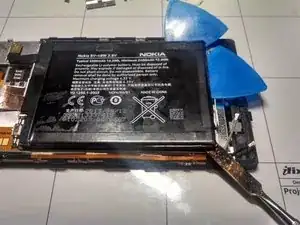
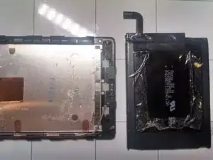
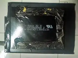
    • The battery is adhered quite strongly to the assembly.

    • A couple rounds of hot iOpener application followed by aggressive prying with plastic picks and metal tools was required to remove the battery.

  16. aoKWktQZUCpnUSrG
    aoKWktQZUCpnUSrG
    ZYTmpXFNUpZY3KJr
    • Views of The Battery and Bare Touchscreen Assembly

alcs99

Mitglied seit: 11/09/13

5075 Reputation

3 Kommentare

I have a 1520 that we are have problems our of the ear speaker. The owner of the device brought it to us complaining of static in the audio. We replace the speaker and it worked fine but now she's back and the audio is out all together. No sound from the ear speaker. Loudspeaker works great so audio output is functional. Any clues or pro tips you can bestow? Thanks in advance.

Eric Suire -

I have disconnected the connector… I don't have any idea of how getting back to the motherboard..! Someone help plz

Hussein -

It may be prudent to add a note to use the picks directly next to the back frame rather then just say from the corner. In my efforts to remove the back, I decimated the screen and now have to get a new one….

Jonathan Walker -