Einleitung

Verwende diese Anleitung, um das Gehäuseoberteil auszutauschen. Am Ende dieser Anleitung findest du die Beschreibung, wie das Touchpad übertragen wird

  1. qPsGdXwUZZBT6RJa
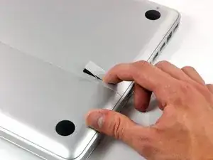
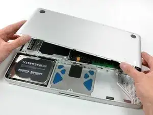
    • Lege die Oberseite des Gehäuses mit geschlossener Klappe auf eine glatte Oberfläche.

    • Drücke den Verschlusshebel auf der geriffelten Seite der Klappe in das Gehäuse des MacBooks, bis du den Verschlusshebel auf der anderen Seite greifen kannst.

    • Öffne den Verschlusshebel so weit, dass er senkrecht steht.

    This is not a a1278 unibody MacBook Pro. A1278 MacBooks backs are one solid metal piece not two separate pieces. This guide is for a different MacBook Pro.

    Brad Burgeson -

    This guide isn’t for a pro; it’s a MacBook unibody.

    Nicholas -

    So, it turns out that Apple used the model code A1278 for quite a few different Mac models, including both Pro and non-Pro versions! This guide is for the non-Pro Macbooks. There’s also one for the Pro models with the same A1278 identifier.

    tempelmann -

  2. Pf4wGUpXWyJ3tAfH
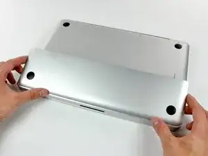
    • Die Bodenklappe sollte nun ein kleines Stück offen stehen.

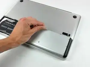
    • Die Klappe kann nun nach oben aus dem Gehäuse des MacBooks genommen werden.

  3. WkwQip2DfR1iJLMX
    • Versichere dich, dass sich die Entriegelung der Klappe in senkrechter Position befindet, bevor du weitermachst.

    • Ziehe an der weißen Plastiklasche und damit den Akku gerade nach oben und aus dem Laptop.

    Great tutorial ! great step !

    Leo Etcheverry -

    Even though it’s specifically stated, you have to make sure the access door latch is vertical or the battery won’t be removable.

    Henry Kim -

  4. mgYUuNTR1BjI1A6i
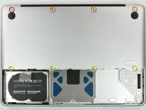
    • Entferne die im Bild gezeigten acht Schrauben, die die Bodenplatte mit dem Rest des Gehäuses verbinden:

    • Eine 3 mm Kreuzschlitzschraube.

    • Drei 13,5 mm Kreuzschlitzschrauben.

    • Vier 3,5 mm Kreuzschlitzschrauben.

    On my model, it seemed the top-left was 3.5mm and the bottom 4 were 3 mm.

    Jim -

    Make sure you have a good quality Phillips screwdriver. Mine had removable tips and had a small play at the connection. As a result I didn't have a good feel and damaged my screws (those securing the fan and the top left in step 23). Game over for me installing new thermal paste...

    Be very carefull with your screws! Especially those on the inside.

    Nickolas Michelinakis -

    You can get away with a Phillips #00 for many of the screws involved but the 4 at the bottom case split are likely to strip if you don’t use a JIS #00 or, in a pinch, a Phillips #000.

    Bill Cole -

    I used the Phillips #00 tip from my Pro Tech Toolkit, and it worked well enough. But yes, maybe #000 might have been better on the lower row of screws. Note to myself: Always read the comments first.

    Les Kitchen -

    When replacing these screws, the order to replace them in is as follows:

    1, Top left

    2. Top right

    3. Top center-left

    4. Top center-right

    5. Bottom center-right

    6. Bottom center-left

    7. Bottom right

    8. Bottom left

    I hope this information is helpful.

    facebook -

    I followed my usual process of putting in all the screws loosely, then tightening them gradually in distributed pattern, to help ensure that the panel settles in place evenly. But maybe some orders are better.

    Les Kitchen -

  5. EZrPgfOVIaaIsXLR
    • Hebe die Bodenplatte mit beiden Händen an und entferne sie vom oberen Gehäuse.

    Thanks for the guide!

    It's implicit in the two photos, but worth mentioning because it blocked my progress in this step for a bit: You have to put the release latch back into its horizontal, closed position before you can lift off the lower-case panel.

    Les Kitchen -

  6. UnfTVKa4kGgLhmpS
    • Ziehe den Stecker am Kamerakabel gerade aus seinem Anschluss heraus und trenne ihn ab.

    • Ziehe beim Ablösen des Steckers nicht am Kabel.

    Be EXTREMELY careful when removing and re-inserting the 'camera' cable. The contacts can be easily bent beyond repair if you try to force it back in. Damaging this cable at this connection or near the display may disable your ability to use your iSight camera, AND both your Bluetooth and WiFi. I had to pay apple $300 to replace the entire display assembly because one prong was faulty, causing my WiFi card to not be recognized.

    seanheff17 -

  7. xORcdpjYmZYWrNAc
    xORcdpjYmZYWrNAc
    Dm5qBsfLdS1OVoer
    • Hole das Kamera-Datenkabel aus seinem Kanal am optischen Laufwerk heraus.

    Although I ordered the screen for an A1278 MacBook Unibody Aluminum, the screen glass was marked as a MacBook Pro. The iSight/WiFi /BT cable was about an inch longer than the Macbook one and took a bit of creative re-routing, but everything works fine.

    tjod -

    has it got the airport and bluetooth modules built in separately in the display assembly as in the macbook late 2008 and mbp mid 2009?

    fericcio -

  8. 6FQppPtEshmRXyuq
    6FQppPtEshmRXyuq
    HLtfrIbButKCKkVh
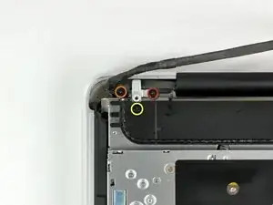
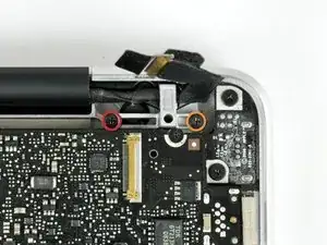
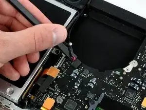
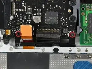
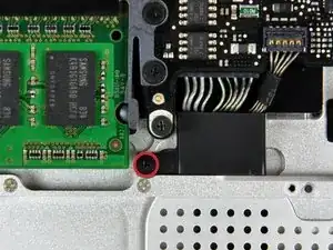
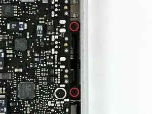
    • Entferne folgende Schrauben, mit denen das Kamera-Datenkabel und der rechte Lautsprecher am Gehäuseoberteil befestigt sind:

    • Eine 9,9 mm lange Kreuzschlitzschraube, nur teilweise mit Gewinde

    • Eine 9,6 mm lange Kreuzschlitzschraube mit vollständigem Gewinde

    • Eine 4 mm lange Kreuzschlitzschraube

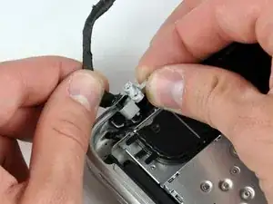
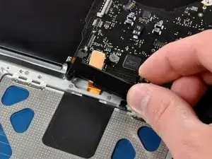
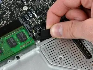
    • Schiebe die Halterung des Kamerakabels unter dem Tieftöner heraus und entferne es vom Computer.

    • Im iSight-Kabel befindet sich eine Öse, durch die die Schraube ganz links in den Bildern geht.

    "orange" is the short one, that goes in the middle ;)

    Riesling -

    My model has different bracket, you need to remove the subwoofer first

    Andrea Ghensi -

    1. With my Laptop, the left screw was partially threaded, not the right one. 2. Before removing the camera cable bracket, I needed to unscrew the subwoofer.

    Edgar Fuß -

  9. dUR61OdDgcqO6ZhU
    dUR61OdDgcqO6ZhU
    CVDUNKbRkXIbkxIB
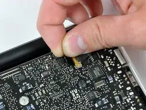
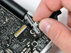
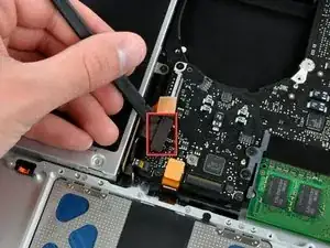
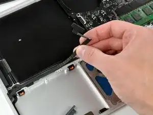
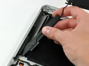
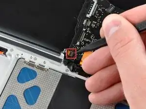
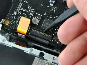
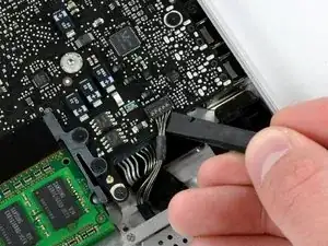
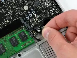
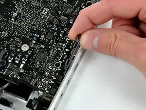
    • Fasse die am Sicherungsbügel des Displaydatenkabels befestigte Zuglasche und klappe ihn zur Seite mit der Stromversorgung des Computers hin auf.

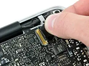
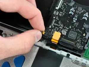
    • Ziehe den Stecker des Displaydatenkabels gerade aus seinem Anschluss heraus.

    • Ziehe den Stecker nur gerade vom Stecker weg, aber nicht nach oben.

    i can't understand what I need to do in this step, I'm afraid with this step, i think i can "hurt" my mac and i don't want to do that, anyone knows what i need to do?

    Thanks

    Lucas Borges -

    There is a steel 'latch' that flips over from the left side of the connector, to the right side. After you flip this latch over, the cable will easily slide out.

    madmaxmedia -

    as I pulled the monitor cable out of the bracket after flipping the lock over one side of the bracket broke loose. Now the monitor will not turn on. Can anyone help?

    boldtu -

  10. KX4fAOE6kkiQnPIE
    KX4fAOE6kkiQnPIE
    ocp6hFJoAXBGxWtU
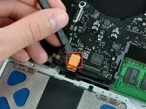
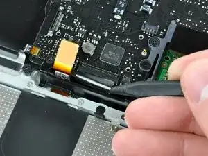
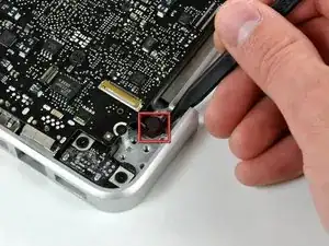
    • Entferne folgende zwei Schrauben von der Halterung des Displaydatenkabels:

    • Eine 7 mm lange Kreuzschlitzschraube

    • Eine 5 mm lange Kreuzschlitzschraube

    • Hebe die Halterung des Displaydatenkabels aus dem Gehäuseoberteil heraus.

    Note for Step 10 during reassembly: Be careful when replacing the screw for the display cable bracket closest to the magnetic power cord receptacle. The interior magnet might attract the screw causing the screw to get pulled under the DC power circuit board which might then require that you disassemble things again to retrieve the screw.

    wintermute -

  11. JZwrRypptntvcRW6
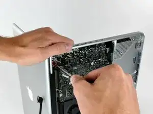
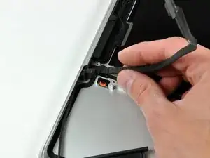
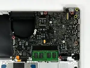
    • Entferne die beiden äußeren 6 mm langen Torx Schrauben, mit denen das Display an jeder Seite am Gehäuseoberteil befestigt ist (also insgesamt vier Schrauben).

    Hey guys, with these older models Do Not interchange different colored LVDS cables. Note the connector here is gold, do not use a silver connector on a gold one or vice versa. I fried a logic board this way on an A1278. Note that the core i7 lvds connector is different than the core i5.

    rjpoirier_nb -

    I never thought that I’d be required to use PB Blaster to remove computer screws. Had to use two tiny drops for each screw, letting it soak in for 20 minutes or so. The display screws, coated with blue thread lock, did not want to budge. I was so fearful that I would strip them using a T-6 driver. Ended up using a 1/4” drive ratchet with a T-6 bit, pressing down firmly and blocking the MacBook from turning with my elbows. I’ve had a lot of experience doing this kind of work, but wow!

    randy3833 -

  12. 3hMFv5xctPAx6bqU
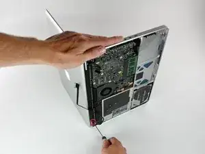
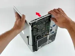
    • Öffne das MacBook, so dass das MacBook rechtwinklig zum Gehäuseoberteil steht.

    • Stelle das geöffnete MacBook wie gezeigt auf die Arbeitsfläche.

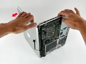
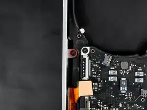
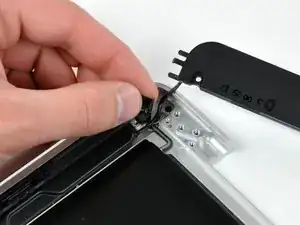
    • Halte das Display und das Gehäuseoberteil mit der linken Hand zusammen und entferne die 6 mm lange Torx Schraube von der unteren Displayhalterung.

  13. UENnAHrYGcqTUVrT
    • Halte das Display und das Gehäuseoberteil weiterhin mit der linken Hand zusammen. Wenn du hier einen Fehler machst, kann das lose Display oder Gehäuseoberteil hinfallen, so dass Bauteile beschädigt werden können.

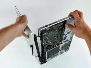
    • Entferne die letzte 6 mm Torx Schraube, mit der das Display am Gehäuseoberteil befestigt ist.

  14. X6xvVBK6giPdMK5I
    X6xvVBK6giPdMK5I
    YZXiaPDuWVTfRJvE
    qOX2lhZEtxKWCLNr
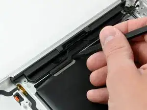
    • Greife das Gehäuseoberteil mit der rechten Hand und drehe es leicht zur Oberkante des Displays hin, so dass die obere Displayhalterung aus der Kante des Gehäuseoberteils herauskommt.

    • Drehe das das Display leicht vom Gehäuseoberteil weg.

    • Hebe das Display vom oberen Gehäuseteil weg, achte dabei darauf, dass sich keine Halterungen oder Kabel verfangen.

  15. OheOqOn6lNyjKCSM
    OheOqOn6lNyjKCSM
    qlImGnIwwSPLGcnO
    • Bei manchen 2.0 GHz A1278 MacBook Unibody Logic Boards ist nicht der nötige Anschluss für das Flachbandkabel vorhanden, das die Tastaturbeleuchtung mit dem Gehäuseoberteil verbindet. Im ersten und zweiten Bild sind Logic Boards mit bzw. ohne den Anschluss gezeigt.

    • Wenn dein Logic Board diesen Anschluss nicht hat, wird deine Tastatur zwar funktionieren, aber die Beleuchtung nicht.

    • Wenn dein Logic Board diesen Anschluss nicht hat, aber das Gehäuse, das du einbauen möchtest, dann schiebe das Flachbandkabel der Tastaturbeleuchtung beim Einbau des Logic Boards in das Gehäuseoberteil einfach aus dem Weg.

    is it still possible to have a backlight keyboard, even if theres no socket installed?

    nightwalkerosfp -

    I would like to know as well. Can a socket be soldered to the board in this spot?

    metalman141 -

    I dont think so coz if apple havent soldered necessary driver chip and circuit for backlight, there is no need to solder that socket. That chip has to be on other side of the board

    Oleg R -

    Yes I believe it can as that is just power for the backlight I believe.... but I have never done this mod to a macbook without the socket.

    Nathanael -

    The socket for the backlight was snap off when I was removing the ribbon cable. Does anyone know where can I get a replacement for the socket?

    Ryan Lim -

    If you have the skill to solder a new connector on, the best option would probably be to look for a donor motherboard.

    Bagel -

  16. ppZWjRHLQIGKnCcF
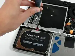
    • Entferne die einzelne Kreuzschlitzschraube, mit der die Festplattenhalterung am Gerät verschraubt ist.

    • Diese unverlierbare Schraube bleibt in der Halterung hängen.

  17. aqXCuJX1S2JPdcOa
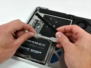
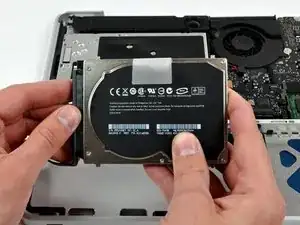
    • Hebe die Festplatte an ihrer Zuglasche soweit an, dass du die Halterung fassen und entfernen kannst.

    • Hebe die Festplatte aus dem Gerät heraus, achte dabei auf das Verbindungskabel zum Computer.

  18. BYrJWMZiPwfcVq2C
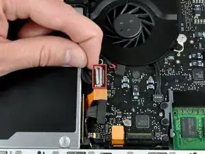
    • Ziehe den Stecker am Festplattenkabel gerade von der Festplatte weg und trenne die Festplatte ab.

  19. xAAWGW1LmJUlkFJG
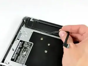
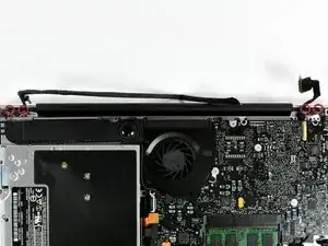
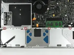
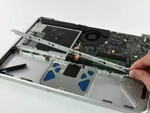
    • Entferne die vier 10,3 mm langen Kreuzschlitzschrauben, mit denen die mittlere Trennleiste am Gehäuseoberteil befestigt ist.

    Need to add a step above this to remove the bottom cover.

    Daniel Zimble -

  20. R2XZFdFZpEfkTptw
    • Hebe die mittlere Trennleiste aus dem Gehäuseoberteil heraus.

  21. FxVjUBSNswUTaDlA
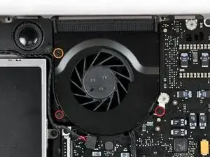
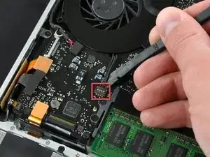
    • Entferne folgende drei Kreuzschlitzschrauben, mit denen der Lüfter am Gehäuseoberteil befestigt ist:

    • Zwei 5 mm lange Schrauben

    • Eine 7 mm lange Schraube

  22. I1mtoITgVFl1UPoi
    I1mtoITgVFl1UPoi
    pdEkqQ5ZUej2R3Q6
    1GnMntUbPkJZ2GdF
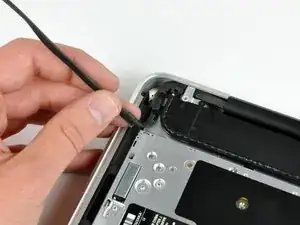
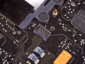
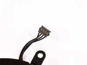
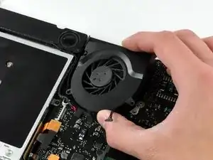
    • Heble den Lüfterstecker mit einem Spudger gerade nach oben aus seinem Anschluss auf dem Logic Board heraus.

    • Es geht besser, wenn du den Spudger axial unter dem Lüfterkabel verstehst, um den Stecker zu lösen.

    • Der Lüfteranschluss und der Lüfterstecker sind im zweiten Bild und dritten Bild zu sehen. Arbeite vorsichtig, damit der Kunststoffanschluss des Lüfters nicht aus dem Logic Board bricht, wenn du den Stecker nach oben heraushebt. Dein Logic Board sieht vielleicht etwas anders aus als im zweiten Bild, der Anschluss ist aber gleich.

  23. gEQm4YyIFTsNNfIW
    • Hebe den Lüfter aus dem Gehäuseoberteil heraus.

  24. 2LMCPDAw4WyuZSi1
    • Heble den Stecker des Tieftöners mit dem flachen Ende des Spudgers gerade vom Logic Board nach oben.

  25. XjGfFufIZcI54LAk
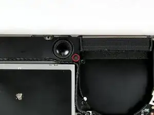
    • Entferne die einzelne Kreuzschlitzschraube, die den Tieftöner am Gehäuseoberteil befestigt.

    My subwoofer has two screws

    Arbera Barbera -

  26. kKiY2Zn6btSpSmST
    • Der Tieftöner ist immer noch mit dem rechten Lautsprecher verbunden, entferne ihn deswegen noch nicht ganz.

    • Hebe den Tieftöner vom optischen Laufwerk ab und lege ihn über den Computer.

  27. kQt54BmUxtHJekcZ
    • Heble den Stecker des optischen Laufwerks mit dem Spudger gerade nach oben vom Logic Board weg.

  28. idFdNZUqmVolZUhi
    • Heble den Stecker am Festplattenkabel mit dem flachen Ende des Spudgers nach oben vom Logic Board weg.

  29. R3QrsL3ytapXRlDt
    R3QrsL3ytapXRlDt
    63JoWo2NAV14jHXD
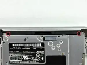
    • Entferne die drei 2,5 mm langen Kreuzschlitzschrauben, mit denen das optische Laufwerk am Gehäuseoberteil befestigt ist.

  30. IPFJZJSnaFqXftPV
    • Hebe das optische Laufwerk an der rechten Seite an und ziehe es aus dem Computer heraus.

  31. sJDI4xviUYi4yrKr
    sJDI4xviUYi4yrKr
    4ip1DDTlFE3EjLwm
    • Löse das Festplattenkabel aus der Klebeverbindung zum Gehäuseoberteil und manövriere den Halteblock aus Kunststoff aus dem Gehäuseoberteil heraus.

    • Das Festplattenkabel und der Halteblock sind miteinander verbunden.

  32. Cs3TawrZTSQry5J4
    Cs3TawrZTSQry5J4
    vC4xoCgSwKrwY11O
    wRTQORwZJPNLv6tZ
    • Ziehe das kleine Stück von schwarzem Klebeband zurück, welches das rechte Lautsprecherkabel bedeckt.

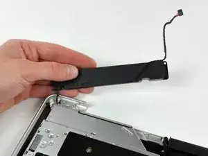
    • Heble den rechten Lautsprecher mit der Spudgerspitze aus der Klebeverbindung zum Gehäuseoberteil.

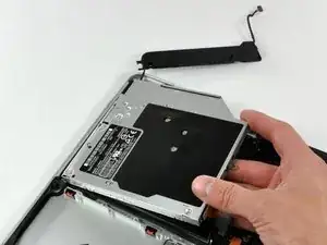
    • Hebe die Einheit aus Tieftöner und rechtem Lautsprecher aus dem Gehäuseoberteil heraus.

    I left it in place. It was not necessary to remove it for replacement of the keyboard.

    Arbera Barbera -

  33. hIOZAsCTyKwVSkFW
    hIOZAsCTyKwVSkFW
    jwtDusIxRePj4q5J
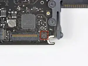
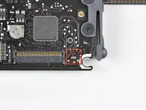
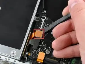
    • Klappe den Sicherungsbügel am Anschluss des Flachbandkabels zum Infrarot-Sensor mit der Spudgerspitze hoch.

    • Ziehe das Flachbandkabel zum Infrarot-Sensor gerade vom Logic Board weg.

    Pull the IR sensor ribbon cable straight away from the logic board.

    Could be useful with a comma

    Vamos Goo -

  34. MUgF2yWqLPIeRIUB
    • Heble den Stecker des Trackpads mit dem flachen Ende des Spudgers gerade nach oben vom Logic Board weg.

  35. YLSxVeRs1ZN51eEw
    YLSxVeRs1ZN51eEw
    wrTJ4RjvXDVMOUXr
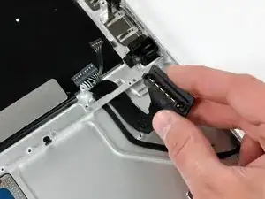
    • Klappe den Sicherungsbügel am Anschluss für das Tastatur-Flachbandkabel mit der Spudgerspitze hoch.

    • Ziehe das Tastatur-Flachbandkabel gerade aus dem Anschluss heraus.

    When you are on the way back, this is where you can connect the keyboard lighting. You put the flat cable from the new keyboard into the connector directly to the right of the one for the keyboard ribbon cable. It shows itself!

    Arbera Barbera -

  36. rtRlgopI1bqsbogR
    rtRlgopI1bqsbogR
    Wc5AMgsRgaqGYqn2
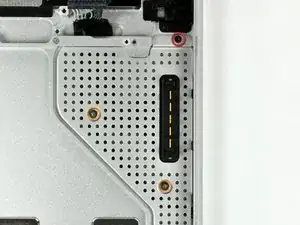
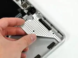
    • Entferne die beiden 5 mm langen Kreuzschlitzschrauben, mit denen die Halterung des Tastatur-Flachbandkabels am Gehäuseoberteil befestigt ist.

    • Hebe die Halterung aus dem Gehäuseoberteil heraus.

  37. ORdACJPNvJgwUH1s
    ORdACJPNvJgwUH1s
    nEMO6TnAFnN4PM1w
    • Entferne die einzelne Kreuzschlitzschraube, mit der die Abdeckung des Akkukabels am Gehäuseoberteil befestigt ist.

    • Entferne die Abdeckung des Akkukabels vom Gehäuseoberteil.

  38. QI3PbUcyGmAX2iJS
    • Heble den Stecker am Kabel der Akkuanzeige mit dem Spudger gerade nach oben vom Logic Board hoch und trenne ihn ab.

  39. II3CM6yKXZfnIxwO
    • Ziehe den Stecker am Akkukabel gerade vom Logic Board weg und trenne ihn ab.

    • Wenn du den Stecker nicht mit den Fingern fassen kannst, dann nimm eine Pinzette oder einen Spudger zu Hilfe.

  40. GXvFks43SnMlooF6
    GXvFks43SnMlooF6
    fhHD2dSnHcrpmENu
    • Entferne die beiden 4 mm langen Kreuzschlitzschrauben, mit denen der Clip des unteren Gehäuseteils am Gehäuseoberteil befestigt ist.

    • Hebe den Clip des unteren Gehäuseteils aus dem Gehäuseoberteil heraus.

    I didn't have that part in my MB at all

    grze -

    Yup me either

    Nick MG -

    AOL. E..g. mine was lacking this part (and its mounting holes) too.

    Edgar Fuß -

    I think this is the wrong photo. The part you have to remove is a bridge above the microphone.

    Roel Hoek -

  41. SdTtNxqKrPSieEVA
    • Löse das Mikrofon mit der Spudgerspitze vom Gehäuseoberteil ab.

    It might be worth noting the microphone is glued to the Upper Case.

    Edgar Fuß -

  42. iNcXOF2IsQDCDKqE
    iNcXOF2IsQDCDKqE
    mijFhkBIXKrY24xo
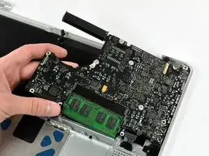
    • Entferne folgende fünf Kreuzschlitzschrauben, mit denen das Logic Board am Gehäuseoberteil befestigt ist:

    • Vier 3 mm lange Schrauben

    • Eine 3,5 mm lange Schraube

    • Entferne die beiden 7 mm langen Kreuzschlitzschrauben, mit denen die Versorgungsplatine am Gehäuseoberteil befestigt ist.

    • Hebe das Logic Board an der linken Seite an und ziehe es aus dem Gehäuseoberteil heraus.

    Note to Step 41: the 3.5 mm Phillips screw and the 3 mm Phillips screw directly opposite were swapped in my MacBook. I believe the screws as indicated in the iFixIt guide are currently incorrect as it seems that the location in my MacBook would be correct as all 3 mm screws engage directly into the top case while the one 3.5 mm screw engages into the black bracket.

    wintermute -

    With my MacBook, the left screw (near the fan) was 5mm (not 3), the other “red” screws were 3mm (as indicated) and the “orange” one was 3.8mm (not 3.5).

    Edgar Fuß -

  43. sHXe5ULRycYmrHrQ
    sHXe5ULRycYmrHrQ
    HPXLjNYoxIBTEAFS
    • Wenn du dein Gehäuseoberteil bei uns gekauft hast, sind die nächsten beiden Schritte nicht notwendig. Die Teile sind bereits vorinstalliert.

    • Entferne folgende Kreuzschlitzschrauben, mit denen die Abdeckung des Akkusteckers am Gehäuseoberteil befestigt ist:

    • Eine 2,5 mm lange Schraube

    • Zwei 1,5 mm lange Schrauben

    • Hebe die Abdeckung des Akkusteckers aus dem Gehäuseoberteil heraus.

  44. b223PPr3IZBUAykE
    • Führe das Kabel zum Akkustecker durch die Öffnung im Gehäuseoberteil und entferne es vom Computer.

    • Wenn bei deinem Ersatz-Gehäuseoberteil die schwarze Halterung in der Mitte nicht dabei ist, dann übertrage sie vom alten Gehäuseoberteil auf das neue.

    During your checkout of your hard work, make sure in System Preferences that the (use all F1, F2 etc. keys as standard function keys) box is unchecked.

    ChasCam580 -

    It was not necessary to remove this item for me. I could remove the keyboard with it in place

    Arbera Barbera -

  45. qNPYgBVYogdUn2BH
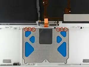
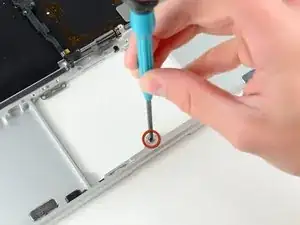
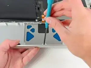
    • Entferne die sechs 1,4 mm Y0-Dreikantschrauben, mit denen das Touchpad am Gehäuseoberteil befestigt ist.

  46. E5CKPaQoirfMC1fe
    E5CKPaQoirfMC1fe
    YvmyQJyH2n5UlP5w
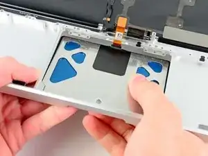
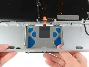
    • Löse vorsichtig die Kante des Touchpads, die am nächsten an der Tastatur liegt aus ihrer Aussparung im oberen Gehäuse, indem du sie von den Halterungen im Gehäuse wegdrückst.

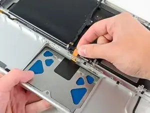
    • Schiebe das Touchpad-Kabel durch den dafür vorgesehenen Schlitz im Gehäuseoberteil.

  47. YlkLlVOqOiBs45ry
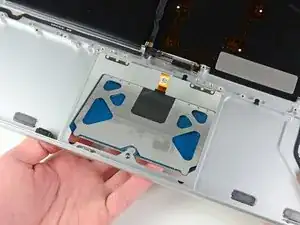
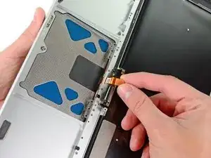
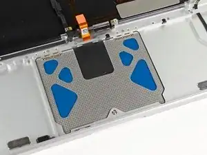
    • Ziehe das Touchpad vom äußeren Rand des Gehäuses weg.

    • Entferne das Touchpad und lege es zur Seite.

  48. Ljuc1IhkaIljBd4d
    • Die nachfolgenden Schritte werden am neuen Gehäuseoberteil ausgeführt.

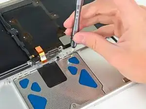
    • Verwende einen Y1-Dreikantschraubendreher, um die mit dem neuen Gehäuseoberteil mitgelieferte 1,2-mm-Stellschraube locker in die Gewindebohrung in der Mitte der Touchpad-Öffnung einzusetzen.

    • Drehe die Schraube erstmal nur mit einer Umdrehung fest!

  49. LiJkXhtYZHXXHypl
    LiJkXhtYZHXXHypl
    oIPnHBVaBW2XMyav
    • Steck das Kabel von deinem alten Touchpad vorsichtig durch den Schlitz in deinem neuen Gehäuse.

    • Halte mit einer Hand das Touchpad-Kabel fest, während du die beiden Halteklammern am äußeren Rand des Touchpads unter die Kante des oberen Gehäuses schiebst.

    • Zieh das Touchpad-Kabel leicht, während du das Touchpad in die Aussparung deines neuen Gehäuses einsetzt.

  50. q4wMXITBTkYCGoBM
    • Dreh eine 1,4-mm-Y0-Tri-Wing-Schraube in jedes der äußeren Löcher des Touchpad ein (insgesamt zwei Schrauben).

    • Den Rest installierst du gleich später.

    • Zieh die Schrauben jetzt fest an und dreh sie dann etwa eine Vierteldrehung zurück – das hilft dir, dein Touchpad in den nächsten Schritten richtig auszurichten.

  51. URRQsOi2XnKin3Ed
    • Während du dein Touchpad immer wieder klickst, dreh vorsichtig die Y1-Tri-Wing-Stellschraube fest, bis sich die Klicks wieder so anfühlen wie im Originalzustand.

    • Du erkennst am Geräusch des Touchpads, dass die Schraube richtig angezogen ist. Wenn die Stellschraube zu locker ist, ist der Druckpunkt des Touchpad zu spät. Ist sie zu fest, klickt das Touchpad zu früh und macht nicht mehr das typische laute Mausklick-Geräusch.

  52. IAQuHHuSFm5QFMVT
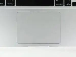
    • Dreh dein oberes Gehäuse als Nächstes um, dass die Tastatur nach oben zeigt.

    • Richte das Touchpad so aus, dass es mittig in der Aussparung des oberen Gehäuses sitzt.

  53. NapXDJFrEiQFrYJ4
    • Zieh die beiden äußeren Schrauben an der Innenseite des Touchpads fest und überprüfe, ob es an der Außenseite des oberen Gehäuses richtig ausgerichtet ist.

    • Wenn die Ausrichtung passt, schraub die restlichen Y0-Tri-Wing-Schrauben an der Innenseite des Touchpads fest.

    • Bevor du dein Gerät wieder zusammenbaust, überprüf, dass die Stellschraube noch so sitzt, dass das Touchpad korrekt klickt.

Abschluss

Arbeite die Schritte in umgekehrter Reihenfolge ab, um dein Gerät wieder zusammenzubauen.

Andrew Bookholt

598569 Reputation

12 Kommentare

On steps 50 and 53, be VERY careful to stop tightening the small, weak Y0 screws when you meet even just a little resistance. I made the mistake of tightening them too hard, and broke the tops off of two of them! Luckily I was able to remove one of the screws, but now one of them is stuck in one of the trackpad holes, unable to be removed.

seanheff17 -

i did upgrade to backlit keyboard by adding the backlight to my keyboard. All works well thanks to this guide. Just try to keep all the screws in theyr place coz you can mistake them very easy and screwing the wrong screw in the wrong holle you may endup damaging the body(i hope it make sense). Good Luck

Nick -

Actually I was looking for a way to remove only the keyboard to clean it, but since there is no guide I followed this one for most of the steps. No need to remove the display assembly and trackpad. But beware that after you remove the logic board and optical drive, you have to remove 3 layers (black, transparent and white) of foil covering the back of the keyboard and then there are like 50 absurdly tiny screws holding the keyboard to the frame. Also there are 2 screws in the upper left corner holding the power button which is connected to the keyboard through a small ribbon cable. After that you can lift the keyboard out easily.

Chris Popov -

cheers mate thats the info i needed.

communit -

Tips: Label Screws by guide step number and size as you go. That way you can easily backtrack and any divergences between your machine's screws and the guide's will be a non-issue.

Also, be careful when removing and tightening screws. I stripped one of my screws and almost needed to call in the pros.

Use common sense throughout your fix. Nothing should be forced. Take breaks and return with a clear head.

Good luck!

pkchitan -

On my new top case, the separator between the dvd drive and the motherboard was missing (the one you can see on the left of step 50 picture). Took the one from the old top case and it worked but I dont know if my new case was missing it or if something is missing in the guide.

Also the screw to adjust the "click" of the trackpad is a nightmare.. I dont know how I managed to make it work but I hope I ll never have to touch it again as I think it is a bit "screwed" now.

Except this ... everything went fine and I can now use my macbook like before which is the most important !. Now I feel more confortable, I may open it again to put a HDD instead of dvd player.

baptistedeclercq -

The keyboard backlite cannot function after replace a 2nd hand keyboard from eBay. Believe the problem was from keyboard itself however the keyboard does have LED layers. And prohibited icon will be shown on screen when F5/F6 Keys (backlite control key) was pressed.

* the guide is good , thank you!

* if you looking for keyboard replacement only, steps 11-14 and 44-53 can be skipped.

* there is more than 40 tiny screws to secure the keyboard. Beware all of them are just too soft. don't play it so hard or you may have trouble to remove all of them.

Kamiiyu -

cheers for the advise

communit -

I followed this guide to replace my keyboard. I removed the backlight from the old keyboard, installed the new keyboard, then replaced the old backlight - it was my keyboard that had failed after liquid ingress, not the backlight.

I confirm that Kamiiyu is correct and I skipped 11-14 & 44-53.

Should also add that on my machine, Step 42, the orange screw was the same as the reds, 3mm. The far left red one was much longer. The bottom red screw had a wider head than the other three.

So just follow it carefully, take notes and take your time.

Thank you iFixit. I now have a fully functional Late 2008 MacBook that Apple deemed "vintage" and beyond repair - all for the price of a replacement keyboard (£15 from ServiceX Ltd in UK who also supported me) and about four hours work! Happy Bunny.

Rex -

For the display data and IR sensor cables, a close-up photo showing the locking lever in the disengaged position would be most useful. I was not feeling comfortable which part of the socket I needed to lift, exactly.

Edgar Fuß -

HelloI

I’ve done almost all steps to remove keyboard must clean it because of Coffee spill containing alot of sugar. If I understand I need now to remove the 51 screws and I will be able to remove the keyboard? Like to know if I can clean it? If so, how do I proceed and what product to use for the cleaning?

Guylaine Lanthier -

Hello Again!

Forgot to mention that because of the spill, the sugar mostly I think, two of the three layers of foil (black and white) where stuck and tore apart while removing the cover of the keyboard. The transparent foil was very dirty but I cleaned it! Where cans I purchase the layers that consist of cover for keyboard?!? Please help I’ve been searching all day on internet to find tutorial for cleaning the keyboard and purchase the cover. Thank you everybody that can help!!!

PS Sorry for my english spelling I’m from Quebec, Canada and I speak french :)

Guylaine Lanthier -