Einleitung
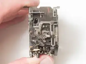
The mirror box is a common source of jams for the Super Program. If the mechanism becomes dirty or sticky, latches may not hold the camera in a charged state or may not release the mirror properly when the shutter is fired. Of particular concern are the rubber dampers meant to reduce vibration. They can degrade and become sticky over time seizing up parts of the mechanism. Disassembling, cleaning parts thoroughly and reassembling can usually restore functionality.
Werkzeuge
-
-
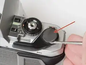
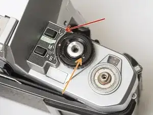
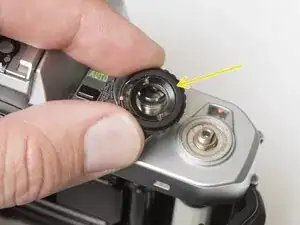
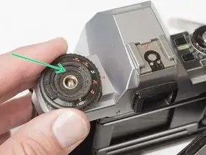
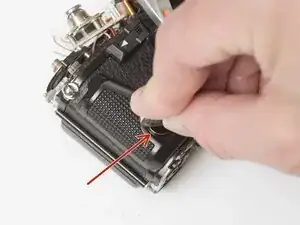
Remove the rubber decorative cap. It is attached with contact cement underneath. Isopropyl Alcohol may be used to soften the adhesive.
-
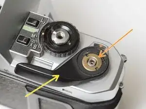
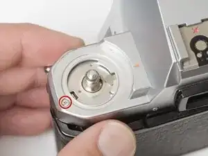
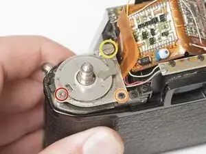
Unscrew the lock nut using a spanner wrench. The lock nut is reverse threaded.
-
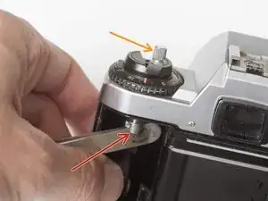
Lift off the advance lever.
-
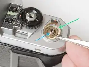
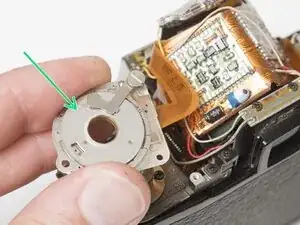
Remove the spring washer.
-
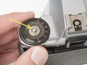
Remove one shim washer.
-
-
-
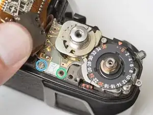
Set the mode dial to the 'L' position.
-
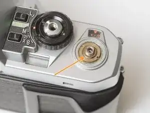
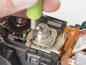
Use a spanner wrench to unscrew the dial lock nut.
-
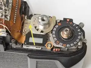
Lift off the mode dial.
-
-
-
Place a rigid object in the fork.
-
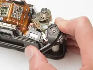
Unscrew the rewind lever.
-
Use a spanner wrench to remove the lock nut.
-
Lift off the exposure compensation dial.
-
-
-
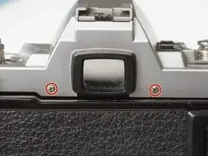
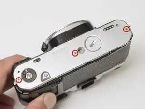
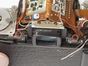
Remove two screws on either side of the eye piece.
-
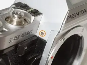
Remove two screws on either side of the lens mount.
-
-
-
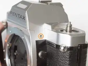
Remove one screw by the exposure compensation dial.
-
Use a spanner wrench to remove the lock nut under the advance lever.
-
Lift off the top cover slowly. It is still attached by one wire.
-
Unsolder one gray flash sync wire.
-
-
-
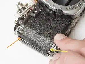
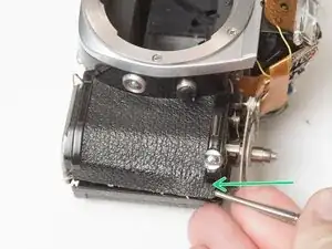
Use a nickel or other large coin to remove the hand grip.
-
Drip isopropyl alcohol along the edge of the leatherette to soften the adhesive.
-
Use a dull scraper to lift one corner and pull off the panel.
-
Repeat on the rewind side of the camera.
-
-
-
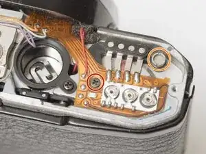
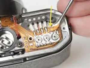
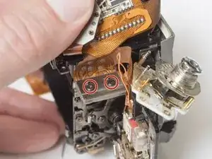
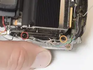
Remove one M1.7 x 4.5 mm screw.
-
Remove one slotted screw.
-
Use isopropyl alcohol to soften the adhesive under the flex PCB.
-
Gently lift the PCB until it is free from the camera body.
-
-
-
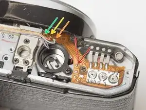
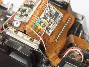
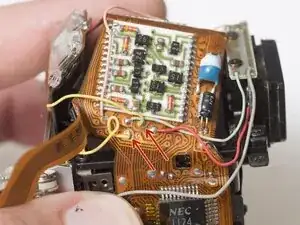
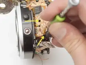
Unsolder one red wire.
-
Unsolder one light blue wire.
-
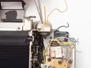
Unsolder one orange wire.
-
Unsolder one purple wire.
-
-
-
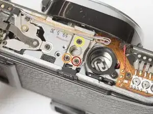
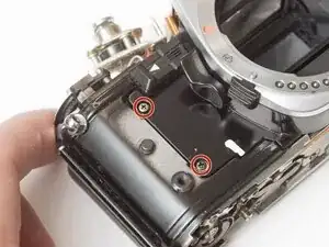
Remove one M1.7 x 4.5 mm screw.
-
Remove one M1.7 x 5 mm screw.
-
Remove one countersunk M1.7 x 5.5 mm screw.
-
Lift the contact terminal free from its seat.
-
Remove the tripod mount.
-
-
-
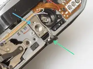
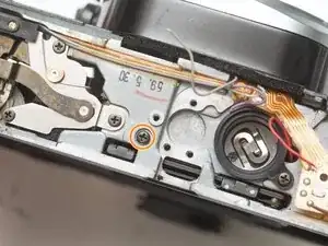
Remove one slotted screw.
-
Remove one M1.7 x 4 mm screw.
-
Loosen one slotted screw (this will remain connected to the assembly).
-
Lift the ISO resistor assembly off the rewind post. It is still attached by a flex PCB.
-
-
-
Remove one M1.7 x 2.5 mm screw. It is only accessible when the mode dial is in the 'L' position.
-
Remove one crosshead screw.
-
Lift the LCD out of the way. It is still attached by a flex PCB.
-
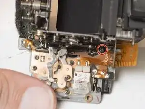
Remove one M1.7 x 2.5 mm screw.
-
Remove one slotted screw.
-
-
-
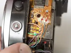
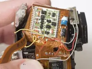
Unsolder one gray wire.
-
Unsolder one red wire.
-
Unsolder one brown wire.
-
Unsolder one white wire.
-
-
-
Wind the shutter
-
Make sure the mode dial unit and ISO selector unit are free from their mounting points.
-
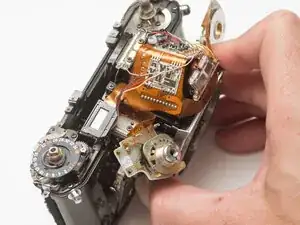
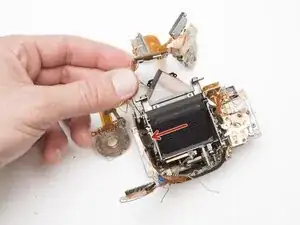
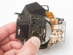
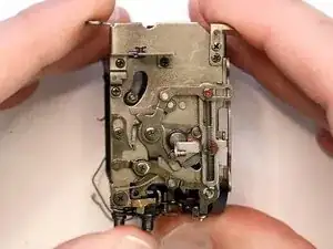
Wiggle the mirror box and front board free.
-
Watch for wire snags as you pull it free.
-
Check for loose shim washers on the front board and note their position.
-
-
-
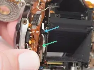
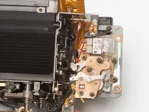
Shutter should be in the charged state.
-
Mirror box should be in released state.
-
Pay close attention to wire routing during install.
-
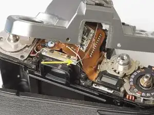
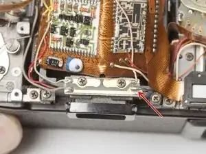
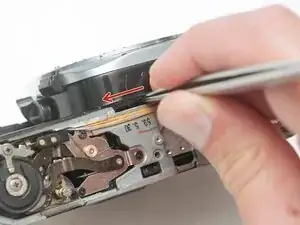
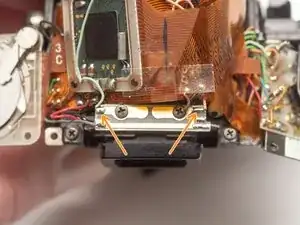
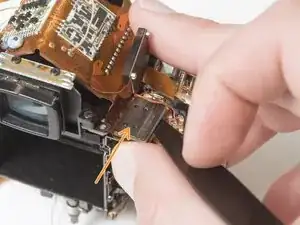
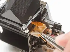
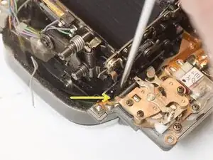
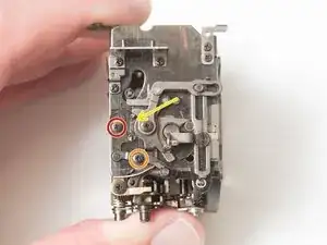
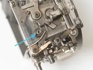
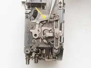
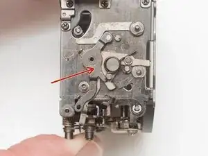
To test the actuation of the mirror and shutter, wind the camera, then insert a tool into this slot and push the release lever to the left.
-
-
-
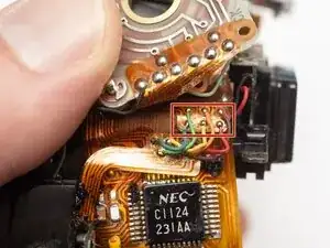
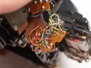
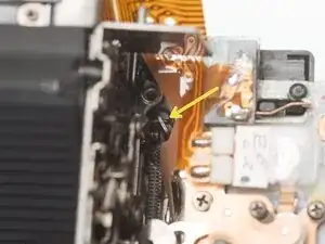
Unsolder one orange and one blue wire for the mirror release solenoid.
-
Unsolder one pink wire for the LCD backlight.
-
Unsolder two purple wires for the TL switch.
-
Unsolder one green wire for the MD switch.
-
-
-
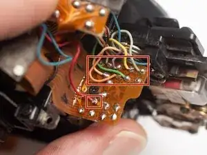
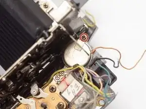
Unsolder the red and black wires for the metering cells in the eye piece.
-
Unsolder pink and green wires for the flash sync connections.
-
-
-
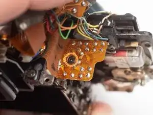
Remove two M1.4 x 2 mm screws.
-
Use a spudger to gently pry off the connector plate.
-
Remove the silicone insulating pad.
-
-
-
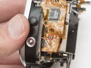
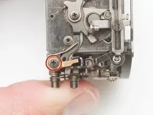
Remove one M1.7 x 4.5 mm screw.
-
Loosen one M1.7 x 4.5 mm screw but leave it in place.
-
Remove two M1.7 x 1.6 mm screws.
-
Remove the mirror governor.
-
Remove one plastic bushing.
-
-
-
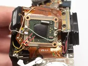
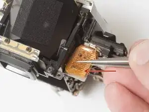
Gently lift away the PCB from the mirror box.
-
The TTL flash metering cell needs to be unseated from the side of the mirror box to free the PCB for removal.
-
-
-
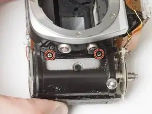
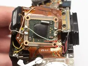
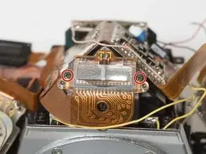
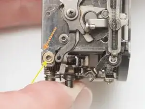
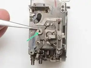
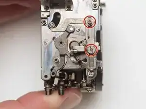
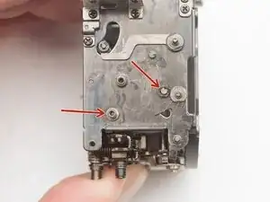
Remove two M2 x 3 mm screws.
-
Remove one M1.7 x 3 mm screw.
-
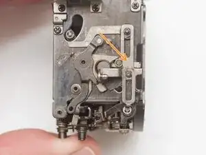
Charge and release the mirror so it is in the taking position (up against the focusing screen).
-
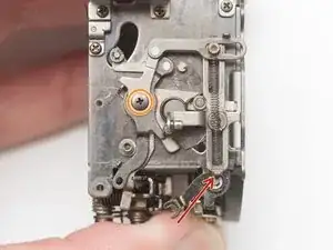
Remove one M1.7 x 3 mm screw.
-
-
-
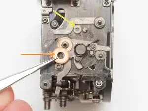
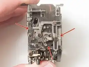
Check the following coupling points between the front lens board and the mirror box.
-
Aperture control.
-
Self-timer lever is above the mirror release latch.
-
Depth of field preview lever.
-
-
-
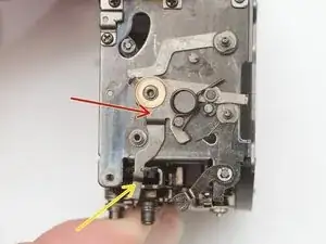
Remove one M1.3 x 2.1 mm shoulder screw.
-
Remove one M1.3 x 2.4 mm screw.
-
Remove coil spring.
-
Remove one shim washer.
-
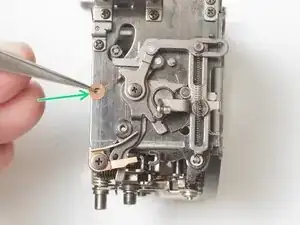
Note the rubber bumper on the pivot post. This should be removed and cleaned before reassembly.
-
-
-
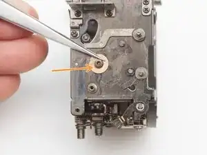
Unhook and remove the coil spring. It may be tacked in place with lacquer.
-
Remove one M1.3 x 4.5 mm screw.
-
Remove the depth of field preview lever.
-
Remove the bushing.
-
-
-
Remove aperture stop-down lever.
-
Remove shim washer.
-
Installation Notes: Ensure the lever foot is placed properly between the mirror flip-up spring and the mirror return lever during reassembly.
-
-
-
Remove two old rubber bumpers.
-
Clean all pivots with isopropyl alcohol.
-
Clean all removed components with isopropyl alcohol.
-
-
-
The mirror mechanism does not need lubrication to operate properly. Most moving interfaces run dry.
-
High friction latching points can be lubricated with a heavy moly grease to reduce wear.
-
Replacement rubber dampers are optional. Silicone tubing cut to length is good source.
-
To reassemble your device, follow these instructions in reverse order.