Einleitung

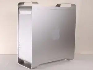
In dieser Anleitung erfährst du, wie man die Hauptstromversorgung des G5 von Apple entfernt.

  1. UaBGTOEf6dyVJEiV
    • Um einen Stromschlag zu vermeiden, schalte den Computer aus und entferne das Netzkabel. Öffne niemals den Computer oder versuche Komponenten im Inneren einzubauen, solange der Computer an ist.

    • Um Verbrennung zu vermeiden, warte mindestens 10 Minuten, um die inneren Komponenten des Computers abkühlen zu lassen.

  2. rBARHUQtVA6lfOWt
    • Entferne alle Kabel, auch das Netzkabel, bevor du den Computer öffnest.

  3. EfcrMHyp4XqEbYsn
    EfcrMHyp4XqEbYsn
    LG2YPVaHQQ1nWjIE
    • Ziehe den Hebel heraus, um die Seitenabdeckung zu entriegeln.

    • Die Seitenabdeckung sollte herausfallen. Wenn dies nicht der Fall sein sollte, ziehe ein wenig an den Kanten der Seitenabdeckung.

  4. mFQ5PLHCQCclToTc
    mFQ5PLHCQCclToTc
    GbBxDZVgNRe2CrnX
    SMxAYMZYyFRqRxWs
    • Entferne das Luftleitelement (die durchsichtige Plastikabdeckung) durch Ziehen am Griff.

  5. IDAAGqatkHs6FhEn
    • Lokalisiere die vordere Lüftereinheit.

  6. Ue42sEAaPLVThCVP
    • Ziehe die Lüftereinheit heraus; sie sollte problemlos herauskommen.

  7. APBogP6JMWqGqlmB
    APBogP6JMWqGqlmB
    IjEMgRgN1NBVvwHG
    • Auf dem Foto ist die Baugruppe rot umrandet (in einem Kasten).

  8. pIUQgt6qMGFVyqFA
    pIUQgt6qMGFVyqFA
    NRx1OuVgLXIqegCg
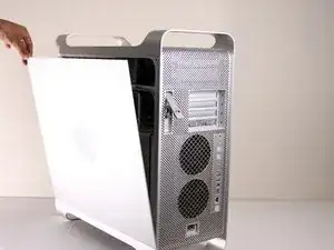
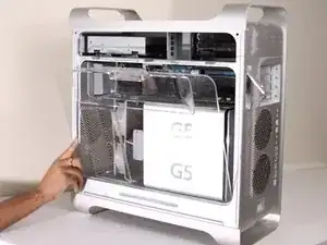
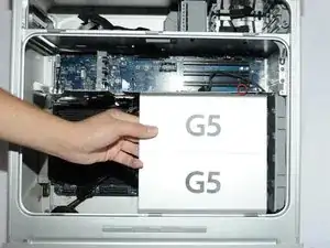
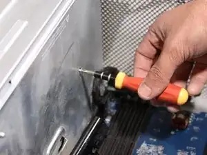
    • Entferne die G5 Metal Abdeckung vom Computer.

    • HINWEIS: Apple hat einen ziemlich zerbrechlichen Kunststoff-Stift eigesetzt, welcher von oben eigesetzt wird und in ein versteckten Teil einrastet. Wenn du diesen Stift entfernst, dann erlischt die Garantie deines PowerMac G5. Ein Ersatz-Stift zu bekommen ist sehr schwierig und nur wenige bekommen den Stift entfernt ohne diesen zu beschädigen.

    • Wenn die Garantie sowieso schon abgelaufen ist, dann kann es dir egal sein, was höchstwahrscheinlich auch schon der Fall ist.

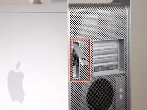
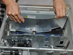
    • Ziehe die Metall-Platte nach links und entferne diese anschließend.

    The whole pin assembly acts like a miniature toggle bolt. The inner part of the pin assembly is actually a short stubby cylinder. When the pin is inserted into the sleeve, it presses on the sleeve and expands it slightly in the processor shield, locking it to the top divider shield.

    I took a tiny drill bit and spun it into the center of the pin just enough so that I could insert a small sharp screw (I used a cup hook) into the pin. All it needed was just a slight tug, and the pin came out of the outer locking sleeve. I used the same screw to remove the outer sleeve.

    Steve -

    I was able to push the bottom part of the shield to the left and unhook the bottom first. I then took a long wooden skewer (18" long) and pushed the center pin out. I then took a pair of needle nose pliers and gripped the two flared ends of the outer sleeve and squeezed them together and pushed the sleeve out of the hole. It was actually pretty easy this way and there was no damage to the pin or the sleeve.

    cuchetti -

    Take a flat head screwdriver and lift a little on the top plate on the top of the cover so as to lift the plastic part slightly. Apply pressure near the top of the plastic keeper and separate it slightly from the metal. Take a box cutter blade and apply pressure around the outside not on the center of the pin. Once you can separate the pin a little from the outside edge take a long strand of glide dental floss and rope it around the pin inside the plastic holder and pull up. Do the same to the outer keeper piece and VOILA!

    Ann Zevely -

  9. H1F6CSACH5Vl2d25
    • Die Lüfter-Baugruppe ist mit einem roten Rand umrandet.

  10. XBuUMdyGOTu1P3EL
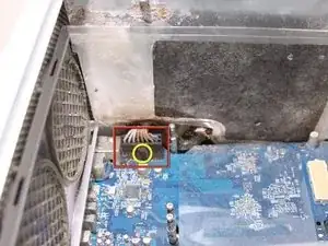
    • Trenne die Verbindung der Lüfter-Baugruppe vom LogicBoard. Wenn eine Grafikkarte eingebaut ist, dann musst du die Verbindung vorsichtig herunterziehen, zwischen der Grafikkarte und dem LogicBoard

    • Das Foto zeigt bereits die getrennte Verbindung der Lüfter-Baugruppe vom LogicBoard, keine Grafikkarte ist auf dem Bild eingebaut. Gelb eingezeichnet ist, wo das Kabel normalerweise angeschlossen ist bzw. wo es liegt.

    To disconnect the cable, it's easier to remove all the cards. I had filled up all 4 slots and I need to space to get my hand in there to disconnect the cable.

    Lawrence -

  11. ei5NFSAMeQA2oFIx
    ei5NFSAMeQA2oFIx
    iEX1ZmUvy1TP3Wfo
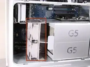
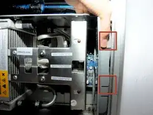
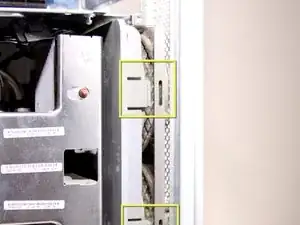
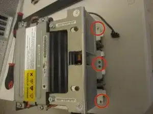
    • Die Halterung der Lüfter-Baugruppe ist Rot mit den beiden Kästen umrandet.

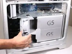
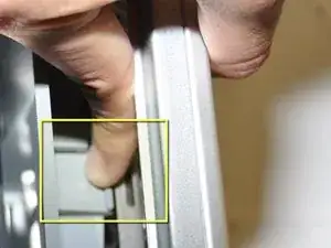
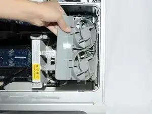
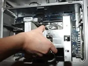
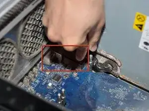
    • Während du diese runterdrückst, musst du die Lüfter zurück ziehen in Richtung Kühlung.

  12. CuTPmTvUlTPNZZJV
    CuTPmTvUlTPNZZJV
    YCQAO35kl154ToAL
    • Nach dem die Baugruppe ausgehakt ist, kannst du die Lüfter herausziehen.

    Before pulling fan, you must unplug fan power cable from upper right-most corner of mother board (connection J45). Carefully pull cable down past the video card's back-side.

    Sam Taylor -

    Thank you for this mention. It seems important, do you have a snapshot of it?

    Is it hard to find/reach?

    And plugging it back in with the new one, any problems?

    Thanks!

    Diana -

  13. rHV4aKaP4nCrfXLF
    • Nachdem die Baugruppe entfernt ist, müsste es so in etwa wie auf dem Bild aussehen.

  14. unuZQVVtxhJuG5Jk
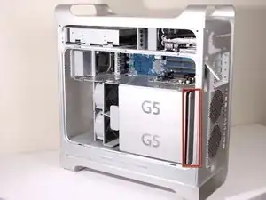
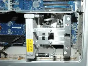
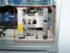
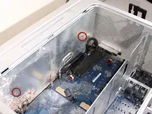
    • Die Kühleinheit des PowerMac G5 ist rot umrandet.

    • Lege das CPU-Gehäuse mit der Öffnung nach oben auf die Rückseite, dann sind die nächsten Schritte leichter.

  15. UnfZrGxywHkyWCvg
    UnfZrGxywHkyWCvg
    camHc21FU1I1mPml
    DmSHQQNRsEsJuGjG
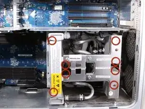
    • Entferne die 8 rot umrandeten T10 Schrauben von der Kühlungseinheit. HINWEIS: Für diese Schrauben braucht man Inbusschlüssel.

    • Das bevorzugte Werkzeug sind Inbusschlüssel mit langem Griff. T10 hat eine Größe von 2,74 mm (der nächstpassende Inbusschlüssel hat eine Größe von 2,5 oder 3 mm) und T15 hat eine Größe von 3,27 mm (der nächstpassende Inbusschlüssel hat eine Größe von 3 mm oder 4 mm). Achte darauf, hochwertiges und geeignetes Werkzeug zu verwenden.

    • Die Schrauben sind teilweise verdeckt, du kannst diese also nicht auf dem Bild sehen

    • Wenn du 3 Arbeitsschritte weiter siehst, erkennst du die genaue Lage der Schrauben.

    • Die Schrauben kann man nur lösen und nicht entfernen. Das ist Absicht.

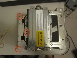
    • Auf den letzen beiden Bilder sieht man eine andere, ausgebaute Version des LCS (Liquid Cooling System - Wasserkühlung) aus einem anderen Blickwinkel, um die 8 Löcher für die Schrauben zu zeigen.

    that looks completely different and I can't unscrew it :/

    grze -

    Did you find a solution for yours? I may have the same problem.

    jaesonk -

    Very difficult on some models.

    Nate Aguilar -

  16. dIuHvGxNu5HwTWQN
    • Ziehe die Kühleinheit mit dem Prozessor gerade nach oben, um eine Beschädigung der Hauptplatine zu vermeiden.

    • Das ist nicht ganz einfach und sollte mit Vorsicht erfolgen, um Beschädigungen zu vermeiden.

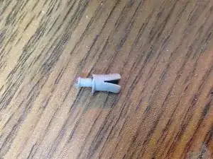
    • Die Hülsen um die 6 Schrauben halten das Teil möglicherweise fest. Nimm in diesem Fall eine Spitzzange und drücke die Hülsen vorsichtig zusammen, bis es sich löst.

    • Ziehe zuerst den Boden und dann die Seite in Richtung des unteren Teils des CPU-Gehäuses, um die untere Kühlmittelmanschette um die Kühlkörperhalterung herum zu verschieben. *Kühlkörperhalterung nicht abgebildet*

  17. m5AnLOVWUlwpwGFJ
    • Ziehe das Kabel ab.

  18. JqoU2Yt3FYiiXQSQ
    • HINWEIS: Hier sind die Abstandshalter ohne installierte Kühleinheit abgebildet, damit du besser erkennen kannst, wo sich die Schrauben befinden. Entferne die unteren zwei Abstandshalter, damit du das Netzteil leichter herausnehmen kannst.

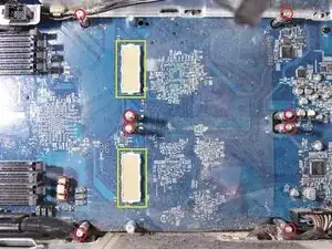
    • Überprüfe die Pin-Verbindungen auf Beschädigungen. Alle gelb markierten Pins müssen gerade stehen und dürfen nicht verbogen sein. BERÜHRE DIE PINS NICHT. Ein verbogener Pin führt dazu, dass sich dein Computer nicht einschalten lässt.

  19. IK35ochICne23muN
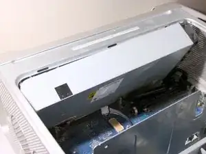
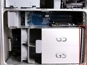
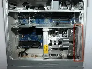
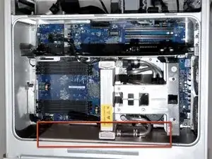
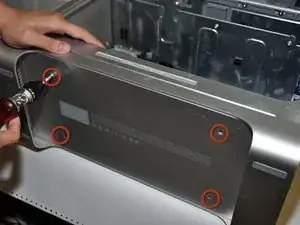
    • Suche das Netzteil im Apple G5 Computer. Es befindet sich unter der Metallplatte unten im Computergehäuse.

  20. aCjIYI6eNc3Tcc3q
    aCjIYI6eNc3Tcc3q
    hqMT5inNApCHuEMX
    qTOVUpLccrbBLCPo
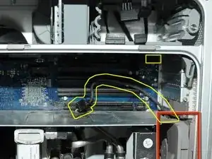
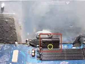
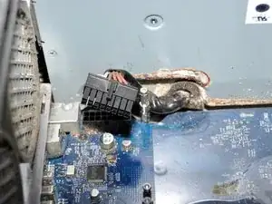
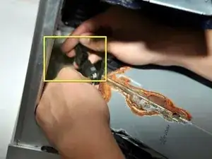
    • Löse die Klammer, indem du sie an der Kante, die am nächsten zu den RAM-Steckplätzen liegt, nach oben ziehst.

    • Ziehe den schwarzen rechteckigen Stecker mit der abgerundeten Oberseite nach außen, um ihn abzuziehen.

  21. Ha4YNV1hPEj4JP6A
    Ha4YNV1hPEj4JP6A
    DOKBOJnZ3VOwNAYL
    3IFxZH25BCtXlUtw
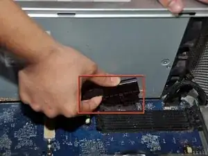
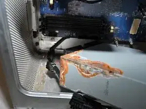
    • Löse den Clip, indem du ihn an der Kante nach oben ziehst.

    • Entferne das Kabel, das sich unterhalb der Kühleinheit befindet. Zieh' es einfach nach außen.

  22. wDkhD2yctkfSnxWl
    wDkhD2yctkfSnxWl
    N5yGDWNUQdZKKDkD
    • Löse die 2 Kreuzschlitzschrauben, mit denen die Abdeckung des Netzteils befestigt ist.

  23. N5Hb2CLKVIUihr3l
    • Entferne die Abdeckung des Netzteils.

    • Dazu musst du das Metall etwas biegen, aber achte dabei darauf, es nicht zu stark zu verbiegen, um Beschädigungen zu vermeiden.

    • Zieh' die Metallabdeckung vorsichtig nach oben und aus dem Computer, damit die Hauptplatine nicht beschädigt wird.

    You don't need to bend anything if you unscrew the lowest studs. The one with pozidrive head is an easy one, but the two round ones which hold the heat sink are quite a challenge. You need to put a nail into the hole which is perpendicular to the stud and turn everything left. You'll unscrew it and the shield comes out without any bending. Step #24 will be easier too.

    Do Mel -

  24. XqMOat4s2HJaHVQY
    • Entferne die 4 Kreuzschlitzschrauben an der Unterseite des Computergehäuses.

  25. tNoFfUMiyvEKCj4m
    tNoFfUMiyvEKCj4m
    qNPBXBdnO2nQXocS
    • Zieh' das Netzteil vorsichtig aus dem Gehäuse.

    • Zieh' das Netzteil nicht komplett heraus, es ist noch mit einem Kabel verbunden.

    Having issue taking out the PSU after removing cover and screws from bottom. It's loose, but the toggle bolts for the LCS seem to be in the way. Did anyone figure a way around this?

    Lawrence -

    ok a little more brute force and i got it out and was able to disconnect the last power cord in the front lower corner.

    Lawrence -

    I Seem too Be stuck At Step # 25 my PSU HAS 9 L-SHAPED BRACKETS ATTACHED TO IT WHICH IS ALSO MOUNTED TO THE MOBO FROM UNDERNEATH....AND AFTER REMOVING ALL 9 T10 TORX SCREWS, WIRES AND CLIPS I STILL SEEM NOT TO HAVE ENOUGH CLEARANCE TO REMOVE THE PSU...... Apple Power Supply PowerMac G5 A1177 710W 614-0368  DPS-710BB---THIS IS THE PSU MODEL THAT I'M TRYING TOO REMOVE AND REPLACE....HAS ANYONE HAD THIS SITUATION AND FOUND A SOLUTION....ALLAN..6/25/16

    Allan Sinclair -

    i broke the connector on the sensor board for the plastic cover, which is glued to the metal body next to the right slot where the plastic cover goes in. the cable is routed around the right, behind the seal. make sure to disconnect this cable before you remove the psu!! now i need to solder the connector back on :(

    olivia -

  26. OSbHVgNcRFDrxdSl
    OSbHVgNcRFDrxdSl
    esUuIX6oi6KOVfME
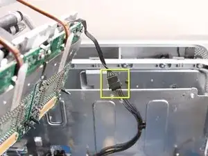
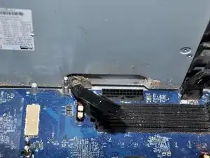
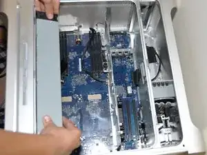
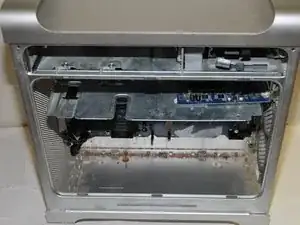
    • Löse das letzte Kabel, das das Netzteil mit dem Computer verbindet.

    • Jetzt sollte sich das Netzteil problemlos aus dem Computer entfernen lassen.

  27. 1FA5MoRyqPBnPCZx
    • Das Unterteil des Computers sollte nach dem Entfernen des Netzteils so aussehen.

Abschluss

Um das Gerät wieder zusammenzubauen, befolge diese Anweisungen in umgekehrter Reihenfolge.

Adam

Mitglied seit: 22/01/10

861 Reputation

12 Kommentare

Swap the Power Supply from G5 2.0 Dual 2004.

lunchbx2 -

Step #16 is kinda confusing on the last paragraph. Can anyone clarify.? Thanks.

Danno -

I followed this guide to replace the PSU in my 2x2.0 PCI G5 - it now works great. I'd like to add that my machine didn't boot right away, I needed to reset the SMU on the main Logic board several times and I also re-seated the RAM chips which seemed to cajole the old beast back into life. I replaced a 450W PSU with a 600W and all seems well so far. Many thanks to the team for posting this ifixit guide.

Chris Allen -

these Apple support notes are worth a look if you run into problems restarting a machine:

http://support.apple.com/kb/HT2652?viewl...

and

http://support.apple.com/kb/HT1436?viewl...

Chris Allen -

Finally - I would also like to add that this guide shows the CPU unit of what I think is one of the crazy liquid-cooled G5s that made a brief appearance in the Powermac range. The same steps still apply for the more common air-cooled models. The only difference being that my machine's CPU units were secured on their mountings with Allen-key type screws - not Torx screws. Doing this repair was not as difficult as you might think, I managed fine and I'm not a tech specialist.

Chris Allen -

The quad core G5 that I have in the UK requires the logic board to be removed before the power supply can be accessed.

Andrew Hinton -

That poor Mac!! All rusted.

Tyler LaPointe -

All this is very interesting, however, if anyone has the voltage and pinouts for a G5 quad CPU (dual/dual core - 2.5Ghz) - LiteOn 1000W TESLAconverter PSU, I would be very, very, interested.

bhbenton -

I love my power mac G5 but recently I encountered a problem with the power supply. It automatically shuts off after 10 mins. I called the service center here in the Phil but sad to say, the unit is already considered vintage. They no longer repair.

Racel Agca -

You should buy one from amazon and do the repair yourself, they’re like $50.

Calvin H -

More like $450 !

Sari -