Einleitung

Der Kühlkörper sorgt dafür, dass der Prozessor kühl und funktionsfähig bleibt.

  1. YgsRrYAFBtYrRivQ
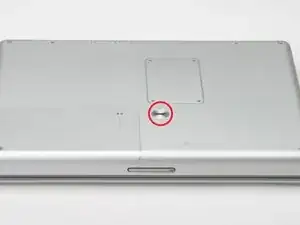
    • Drehe die Batterie-Sicherungsschraube mit einer Münze um 90 Grad nach rechts.

    • Nimm die Batterie aus dem Computer.

    What can I say?

    It is certainly do able. I just completed it. Took me 2 hours. The most important tool you'll need is patience - bag full of patience!!

    Gopal -

    Took 3 1/2 to 4 hours for someone who is handy but has never opened a computer before. Not so bad and it was a fun learning experience.

    Nomad Toes -

    Zitat von Nomad Toes:

    Took 3 1/2 to 4 hours for someone who is handy but has never opened a computer before. Not so bad and it was a fun learning experience.

    Weird. I posted this on Step 1 of replacing the optical drive, but it showed up on the RAM page since Step 1 is the same. Replacing the RAM takes 10 minutes.

    Nomad Toes -

    I also see this on “replacing the battery” :-)

    atarixle -

    I guess, the hardest thing is to find a trustfully shop to buy a new one. You should create a manual how to disassemle the body of the battery and replace the standard round cells inside it.

    atarixle -

  2. R4N3tPJXuHZ3jeoi
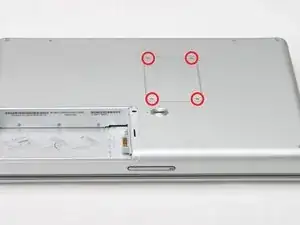
    • Entferne die vier Kreuzschlitzschrauben der Speicherabdeckung.

    • Entferne die Abdeckung vom Speicherfach.

  3. BKmiFChnaJgREW6s
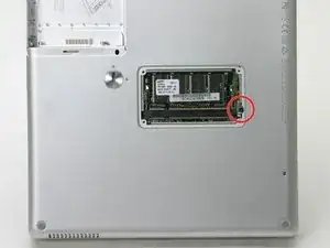
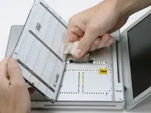
    • Entferne die lange schwarze Kreuzschlitzschraube neben der Speicherkarte.

    • Entferne den kleinen EMI-Finger unter der schwarzen Schraube.

    What is an EMI Finger???

    zdavatz -

    Zitat von zdavatz:

    What is an EMI Finger???

    yeah, good question. I just blew that off - everything else worked just fine - thanks to ifixit for such a great step-by-step!

    springboard -

    Zitat von zdavatz:

    What is an EMI Finger???

    That black screw needs to come out because it goes all the way through the computer into the back of the keyboard. However, I didn't see any EMI finger, unless that's the purpose of the metal directly underneath it. EMI fingers are those little tin foil like things you'll see along the ports inside the computer. They provide shielding from what I presume stand for electro-magnetic interference.

    aratuk -

    Zitat von zdavatz:

    What is an EMI Finger???

    I think the EMI Finger is probably the silver clip that is under the head of the black screw that step 3 tells us to remove.

    Derek Roff -

    EMI stands for electro-magnetic inteference. An EMI finger is a piece of metal that connects two pieces of a metal case together, preventing EMI ("radio waves") from passing in or out. In this case, yes it is the "clip".

    jerrykrinock -

    The black phillips screw is completely stuck on my compulter, and in my frustration, I managed to stripp the screw.. Noe I am concidering drilling it out, this will most likely destroy both the screw and the "EMI finger". Is this a problem? I guess the screw is no problem, but the EMI finger? Or anybody have any ideas to what I could do, I wanted to change my harddrive.. Thanks!

    powerbookg4hdd -

    Dear powerbookg4hdd. This is a very long screw and you could not drill it out. First, try to turn it with needle-nose pliers. If that is too difficult, use a larger drill bit and try to drill the head completely off instead. You're in a very difficult situation. Of course, remove the RAM card to give yourself some working space.

    jerrykrinock -

    Dear jerrkrinock! Thank you for your quick reply. Taking your recommendation, I did not try to drill it out, and after considering several approaches, I used a cutter and changed the "star" screw into a "straight" one. This was successful, and I was able to change the drive. I did not find anything that could be an EMI finger, though.. Anyways, thanks ifixit.som for great guides!

    powerbookg4hdd -

    I believe the clip is referring to the ribbon of grounding material that the plate sits on. You need to move it over to take the long screw out without tearing it. And then you need to lift it and hold it out of the way when you replace the the long screw to avoid pinching it under the head of the screw. TR

    tredding -

    powerbookg4hdd: or anyone else -- i'm in a similar situation. what kind of cutter did you use to re-notch the screw? or is there another way to get this screw out if it is stripped?

    afb -

    To be clear on this step you don't need to remove the long black screw (in fact it doesn't appear possible to remove it completely) just make sure it's been unscrewed as much as possible and then leave alone

    mancunianlad -

    This is correct. The long black screw screws into the keyboard so it does need to be unscrewed, but can be left in place. It may fall out while the laptop is bottom down but if you are working on a towel you'll find it easily.

    Zitat von mancunianlad:

    To be clear on this step you don't need to remove the long black screw (in fact it doesn't appear possible to remove it completely) just make sure it's been unscrewed as much as possible and then leave alone

    emanmb -

    I don't see anything that looks like a clip under this screw. It came out just fine (although it wanted to pull up the padding directly above it when I I pulled it out), but all that's under it is the metal plate it's screwed into, which looks like it is also held down by another screw. Is this what I'm supposed to remove? It certainly doesn't seem to want to come up.

    Calion -

    Should this step specify that the memory door is now to be replaced? At Step 9 the photos show it back in place and yet I didn't see where it was to be screwed back on.

    FWIW, my PB did not have an EMI Finger (assume some earlier repair removed it and did not put it back). Is that a concern?

    kah -

  4. SDuXICZxmojYuKGx
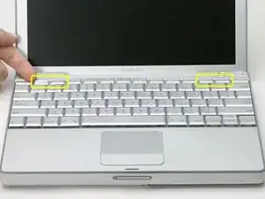
    • Entferne die F1, F2, F11 und F12 Tasten von der Tastatur.

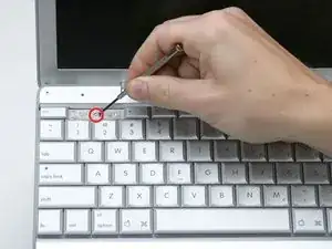
    • Das ist jetzt etwas aufregend, hole tief Luft vor dem nächsten Schritt. Setze deinen Zeigefinger unter die obere linke Ecke der Taste und hebe sie hoch, bis es klickt. Schiebe dann den Finger an die linke Kante und hebe die Taste nach oben ab.

    • Du löst dabei die beiden Laschen links an der Taste aus den beiden kleinen Löchern im Scherenmechanismus aus Kunststoff.

    • Wenn du die Tasten wieder einbaust, setze die Taste direkt über die Stelle wo sie hingehört und drücke sie nach unten, bis sie einrastet.

    once you have removed the little gray stickers, you actually can remove the little screws without popping out the F1/ F2 and F11 and F12 keys. Just pull up the keys a little bit and slip the screw between the keys, a magnetic screwdriver helps.

    Jamba -

  5. PSrwUQPXIOE1ELPG
    • Die Schrauben sind mit einem grauen Aufkleber bedeckt. Löse den jeweiligen Aufkleber mit dem Fingernagel oder einem kleinen Flachschraubendreher ab.

  6. sjCtHVAPx1MjOCmQ
    • Entferne die beiden kurzen Kreuzschlitzschrauben.

    Wish I had bought the magnetic pickup tool, it would really help with getting the very small screws out in step 6!

    reginad -

  7. fmaOywbfBwU2MVcK
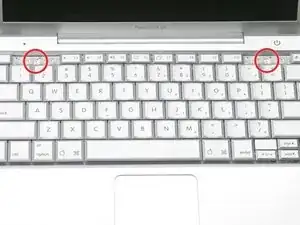
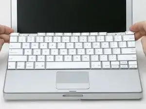
    • Fasse die Tastatur an der "ESC" und "Eject"-Taste und hebe sie behutsam hoch, bis sie senkrecht steht.

    There's some kind of extension to the keyboard in the upper left which slots into the area underneath. Mine was stuckfast and had to be pried loose with a screwdriver. That bent the keyboard, but I manage to get it straightened out somewhat. Any tips for dislodging this piece should it get stuck like mine?

    Paul -

  8. t5hlCOsUSCGenNic
    • Fasse das Tastatur-Flachbandkabel nahe am Anschluss an und trenne es vom Logic Board ab.

    I would not pull up on the ribbon as is being done in the picture. Note that the black pastic base that you see is the connector part that is permanently attached to the ribbon cable. Use a small screwdriver or spudger alternately on each end of the black plastic base to pry and rock it upwards.

    jerrykrinock -

    I agree. I was able to use a needle nose pliers to gently grab the black connector and wiggle the connector from the motherboard.

    Zitat von jerrykrinock:

    I would not pull up on the ribbon as is being done in the picture. Note that the black pastic base that you see is the connector part that is permanently attached to the ribbon cable. Use a small screwdriver or spudger alternately on each end of the black plastic base to pry and rock it upwards.

    emanmb -

  9. li1AIDLSlfFechFw
    • Entferne die drei Kreuzschlitzschrauben innen im Akkufach.

    WORST possible location for the screws. They were tight and the space to get to the screws were so small that all my screwdrivers had to get to it at an angle. So afraid of stripping the screws.

    James Jan -

  10. mYTHGZFNhNNh6PQ2
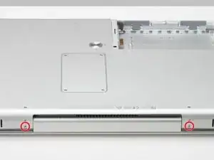
    • Drehe den Computer 90° im Uhrzeigersinn und entferne die beiden Kreuzschlitzschrauben vom Gehäuse.

    • Die äußeren Schrauben sind etwa 7 mm lang.

  11. nDPTDIZteywgJQUq
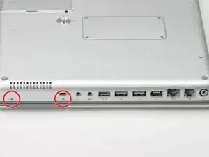
    • Drehe den Computer weitere 90° im Uhrzeigersinn und entferne nur die untere Schraube an jeder Seite des Scharnies.

    I guess this is bottom screw if you have the computer upside-down?

    shortusername -

    That's what worked for me. The illustration is correct or at least this procedure worked for me. =)

    Zitat von shortusername:

    I guess this is bottom screw if you have the computer upside-down?

    emanmb -

    Step 10-these two screws are 5.5 mm with a shoulder

    Step 11--these three screws are 5.5 mm without a shoulder

    Step 12--these two screws are 3.5 mm with a shoulder

    Chuck -

    Don't do what I did.. I had taken both top and bottom screws out before coming upon this site.

    When I had put everything back together again, I unfortunately realized that the top set (towards the bottom of the computer) of screws attach the screen to the frame. On the screen setup there are these prongs that slide into the bottom edge of the frame. My prongs where sitting ontop of where they were suppose to go. I then had to take the computer apart completely again :(

    maruskiewicz -

    I think it is necessary to remove everything here, including the above.(A1104)

    misa Tens -

  12. IQCcudxWlystgoX1
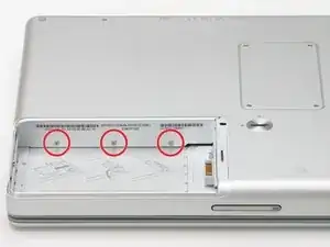
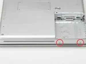
    • Drehe den Computer nochmals 90° weiter im Uhrzeigersinn und entferne die beiden Schrauben an der Außenwand des Akkufachs.

    • Hinweis für den Zusammenbau: es handelt sich um Langhalsschrauben.

  13. doMIVqiMWsxsLpSZ
    • Drehe den Computer herum und öffne ihn.

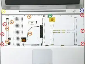
    • Entferne folgende vierzehn Schrauben:

    • Sechs 2,5 mm lange Kreuzschlitzschrauben an jeder Seite des Tastaturbereichs.

    • Fünf 4,5 mm lange Kreuzschlitzschrauben an der linken Seite des Tastaturbereichs.

    • Eine 7 mm lange Inbusschraube in der oberen linken Ecke des oberen Gehäuseteils. (Ein Torx T6 Schraubendreher passt gut)

    • Eine 15 mm lange Kreuzschlitzschraube oben in der Mitte des Tastaturbereichs.

    • Eine 16,5 mm lange Inbusschraube oben rechts im oberen Gehäuseteil. (Ein Torx T6 Schraubendreher passt gut)

    Suggestion: Print the photo on a full sheet of paper and punch small holes through the paper inside each circle. As you remove the screws, push each one through the corresponding hole in the picture.

    LauderdaleMac -

    What are those connectors responsible with? What parts do they connect.

    I need to know this since after my hdd replacement my airport card is not seen in the list of contents:

    I get this massage : "No information found."

    The card is working since I put it in another laptop and it worked there.

    THANK YOU!

    diago -

    Make a full page printout and using sticky tape put the screws (in clusters if easier) where they should go on the photo. In fact I took a blank sheet of paper and did a step by step guide to all screws I took out and then put the screws next to each step header (1,2,3....) and put sticky tape on them.

    mancunianlad -

    FYI there are 14 screws - not 13

    mancunianlad -

    I found that a T7 Torx screwdriver worked better for removing the two hex screws

    slessard -

    I set out tiny dixie cups and marked them for each step wit screws 2-22, including 3 cups for step13, red, orange, and the other 3.

    shon -

    Also, a T6 driver works for the blue and yellow screws, but the 1.5 mm hex head driver is the appropriate driver for those screws.

    shon -

    I think, that the needed Hex is actually a 1/16 inch Hex.

    the 1.5mm works fine but seems to be a littlebit too small (But i can't test it since i do not own 1/16 inch Hex (but that one should be about 1.58mm).

    MrKane -

    Zitat von MrKane:

    I think, that the needed Hex is actually a 1/16 inch Hex.

    the 1.5mm works fine but seems to be a littlebit too small (But i can't test it since i do not own 1/16 inch Hex (but that one should be about 1.58mm).

    That very well may be true. The 1.5 mm hex does go in pretty easily, but I got both screws out and back in with it. I don't have a 1/16 hex either, but that would be interesting to try if anyone has one.

    shon -

    at keyboard left I've a metal piece not show in any powerbook G4 12"... how to tear down it correctly ? I took 2 pictures from another PB with this same piece

    In one I forced it: beneath Its seems to be a screw !!

    How I can upload those pictures ?

    Fernando -

  14. LBAOcDRNBIVXXF5I
    • Dieser Schritt ist sehr knifflig und dein Computer kam dabei ruiniert werden. Der Stecker mit dem roten und schwarzen Kabel (die Stromversorgung) kann leicht aus der Hauptplatine herausgerissen werden. Wenn das passiert, ist eine Reparatur fast unmöglich.

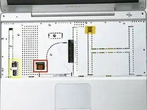
    • Löse die beiden Stücke der Klebefolie von der linken Seite des Tastaturbereichs ab.

    • Die Stecker an den Kabelenden stecken sehr fest in ihren Anschlüssen auf dem Logic Board. Wenn du direkt an den Kabeln ziehst, reißen sie entweder aus dem Stecker ab oder sie reißen den ganzen Anschluss vom Logic Board ab.

    • Trenne sehr vorsichtig die Mikrofonkabel und die Stromversorgung vom Logic Board ab. Heble die Stecker sehr sorgfältig mit einem Fingernagel oder einem Zahnstocher aus ihren Anschlüssen. Achte darauf, dass du nur am Stecker hebelst, nicht am Anschluss.

    What two pieces of foiltape do you mean?

    zdavatz -

    Zitat von zdavatz:

    What two pieces of foiltape do you mean?

    There should be two pieces of foil tape on top of the connectors on the left side. The laptop in the picture was disassembled previously and somebody forgot to put the tape back...

    Miroslav Djuric -

    Is anything can be done if I brooked the power sockets in the logic board during hard drive changing?

    gregk -

    In the picture, the foil is already gone. If your computer has been taken apart previously, as apparently ours has, the foil may be already gone. The photo is missing the markers that are needed to see what they are talking about, but these two connectors are near the left side. The speaker cable has a red and black wire, and the microphone connector has three grayish white wires.

    jerrykrinock -

    YOU DON'T NEED TO DO THIS!!! IT IS DIFFICULT. WHEN YOU PROCEED TO STEP 16, JUST LIFT TOP OFF CAREFULLY AND LAY BESIDE LEFT SIDE!

    jnelson -

    Zitat von gregk:

    Is anything can be done if I brooked the power sockets in the logic board during hard drive changing?

    I need to know this as well. The top socket (red and black wire) broke off the logic board. Can I fix it?

    kristinaksmith -

    Zitat von gregk:

    Is anything can be done if I brooked the power sockets in the logic board during hard drive changing?

    thomsenmusic -

    I pulled the plug off the red and black power leads. I successfully pulled the plug off the board and took it to my apple store. The tech. said that I would need to find the entire power lead..from the button to the plug, or the entire metal piece with everything attached. He doubted that Apple still stocked any of the parts and suggested I look for parts on eBay. I may be able to push the wires back into the old plug but this may not be a stable connection. Any suggestions???

    Zitat von thomsenmusic:

    thomsenmusic -

    As another reviewer suggested you don't need to unplug the 2 cables for the mic and power cables and risk breaking the connectors. Once you have managed to unclasp the casing just - carefully - put the casing to the left side and prop it up so it's standing almost vertically. You will have enough room to access the hard drive underneath.

    mancunianlad -

    I agree with several others here. It is not necessary and not recommended to perform the step 14-unpluggings. Everything worked fine without doing this step.

    suselfunk -

    Zitat von jnelson:

    YOU DON'T NEED TO DO THIS!!! IT IS DIFFICULT. WHEN YOU PROCEED TO STEP 16, JUST LIFT TOP OFF CAREFULLY AND LAY BESIDE LEFT SIDE!

    I agree. I did not disconnect either one either. I propped it against the side of the monitor of the MacBook Pro I was reading these instructions on while doing this repair.

    shon -

    Mine was that way too! No foil.

    Zitat von Miroslav Djuric:

    There should be two pieces of foil tape on top of the connectors on the left side. The laptop in the picture was disassembled previously and somebody forgot to put the tape back...

    emanmb -

    I agree as well. Step 14 can be skipped and I did it that way as it was advised by users here. Just be careful once the plate is free as it is still connected to those wires and they seem fragile.

    Zitat von shon:

    I agree. I did not disconnect either one either. I propped it against the side of the monitor of the MacBook Pro I was reading these instructions on while doing this repair.

    emanmb -

    They must have stopped using the foil tape. Mine did not have it either. I left the connectors alone too as suggested. Not a problem.

    Craig -

    I found it easier to leave these attached and pry them off after partly lifting the top chassis in step 17.

    Kees -

    Note were the tapes are as they do not fully show in the photo.

    Sergio Zori -

    I broke out the power socket here. Even though I tried to hold it down with a plastic dental tool. I believe I have carefully soldered it back to the board. I will know if I did when I get it back together. I quit at step 21 and decided to put it back together. I will use an external optical drive if I ever need one.

    jsparks -

    It might be better to disconnect the connectors after step 18.

    Paul -

    On my PBG4, I found 3 wires attached to the upper case - red and black wires that run to the power button, blue and black wires that run to the mic, and a flat orange cable that runs from the trackpad to a socket on the motherboard. The coloured wires are taped to the upper case, and don't need to be removed. The flat orange connector is directly under the square opening in the upper case, and has loop to help in removing it from the motherboard (which needs to be done). This step was not tricky at all.

    No Name -

    Yes, you don't need to do this step, but you SHOULD gently pull the little loop that is to the right of the yellow box -- separates the trackpad wires from the board. Compare the picture in 14 with the picture in 15 and you'll see the technician did this.

    sciencereporter -

  15. edhkfdmWO5VegjVt
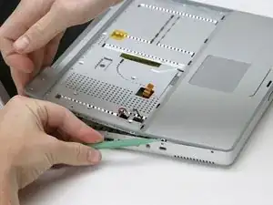
    • Fange in einer der oberen Ecke nahe am Display an, das obere vom unteren Gehäuseteil abzulösen.

    As suggested above this is quite tricky due to the plastic catches towards the front of the case (ie where the trackpad is). Access the front 2 on the right by going in through the empty battery slot and prise away the plastic from the case. That leaves the 2 on the left which are tricky. Use a spudger or flat head screw driver (v careful here though so as not to scratch the casing) to work around the front left casing. Don't give up or despair - it does unlock eventually!

    mancunianlad -

    Heed the warning that this is a difficult procedure. Those little clips were a lot of work (sliced finger trying to get into the case). I was able to do it but with much attention to not break my case. Patience.

    randy29 -

    Maybe mine had been opened before but the cover came off fairly easily. Getting it back on was a little tricky and required some finesse. I was able to get mine off with just my fingers and finger nails.

    emanmb -

    Zitat von mancunianlad:

    As suggested above this is quite tricky due to the plastic catches towards the front of the case (ie where the trackpad is). Access the front 2 on the right by going in through the empty battery slot and prise away the plastic from the case. That leaves the 2 on the left which are tricky. Use a spudger or flat head screw driver (v careful here though so as not to scratch the casing) to work around the front left casing. Don't give up or despair - it does unlock eventually!

    Damo -

    I use a credit card to part the case. works very well

    Damo -

    The aluminum upper case has a grey plastic rim that comes off with it. Running a guitar pick between the plastic rim of the upper case and the aluminum of the lower case made removal easy.

    No Name -

    If you don't do step 14 (and you really DON'T need to), then know that you're not going to be able to remove completely the upper case from the lower. It will be attached by the black/red wires and the gray wires (see my comment in step 14, too, about detaching the wires that connect with the trackpad). I could not lean the upper case against the screen -- my wires were not long enough, I guess -- but since both sets of attached wires (skipping step 14) are on the same side, you can tip it up and hold it whilst you remove the hard drive. Yes, be patient in doing this step. I broke a guitar pick doing this, so you can apply some force, but do so gently. In the end, I'm not sure what I did to get the non-battery side separated, but just kept wiggling it and applying some force near the trackpad. It popped, and I immediately stopped putting on pressure to ensure I did not pull the upper case completely off (separating the wires/connectors referenced in step 14).

    sciencereporter -

  16. eX3NTxyYCmFQrdmL
    • Löse vorsichtig die beiden grauen Kunstoffclips innen im Akkufach, um den rechten Teil des oberen Gehäuseteils abzulösen.

    • Der linke Teil wird ebenfalls von zwei grauen Kunstoffclips gehalten. Sie sind nicht leicht zu lösen, da sie erst sichtbar sind, wenn sie draußen sind. Sie sind in der gleichen Position wie die beiden anderen im Akkufach, aber auf der anderen Seite am Trackpad. .

    • Stecke ein flaches Hebelwerkzeug in die Löcher für die Clips und drücke die Clips nach innen (zum Display hin), so dass sie sich lösen und den linken Teil freigeben

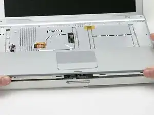
    • Hebe das obere Gehäuseteil vom Computer weg.

    This is not as easy as it looks. You see the four slots in the picturer there -- the two on the end are partially covered by the technician's left and right thumbs. Those are attached to plastic clips that need to be disengaged. You can access the two inside the batter compartment and disengage them using a small flat-head screwdriver, but the two on the left are not accessible. I finally got them to disengage by pulling up near the trackpad.

    jerrykrinock -

    Also there are two small cables on the right side that need to be removed and then reinserted when removing and installed the top case back.

    Andrew Harris -

    upper case won't go out .... it's seems like a metal top obstruct it , because upper case bend when I try to pull out !!

    Fernando -

    The top case will not come completely off without removing the track pad cable connector.

    antonio -

    These instructions neglect to mention that there are two hidden clips on the left side of upper case. They are just like the clips in the battery compartment, but they are hidden from view (they are above the hard drive compartment. So it is necessary to not only pry the bottom case out a little, but also to find the two slots where those clips are engaged, and push them in slightly (with a small nylon pry tool, or very gently with a small flathead screwdriver). You can see one of them in the photo above just to the left of the the trackpad, but the one on the left is blocked (in the photo) by the person's left thumb. It's pretty much in the same location as the two in the battery compartment, just on the left side. Good luck. Took me 15-20 minutes of increasingly more forceful prying before I got lucky and accidentally found the left clip holes. I wish these instructions mentioned them... I've edited them so they do now.

    Donald Aehl -

    I had my hard disk replaced about 6 years ago but I decide to replace it myself this time. I think the service guy must have had a problem with the power socket as this was wobbling on the logic board when I opened it up. I unplugged the mic but left the power (red and black wires) in the board as this was so loose it would have come clean off trying to unplug. I put it all back together and it didn't fire up. In the end I had no choice but to pull the power socket clean off the board as it wasn't making any contact with the contacts on the board. Using a magnifying glass i could see that this wasn't soldered (looked like it was glued) and had two plastic pins. These pins slotted in two holes on the board to align. I the end I just put a bit of superglue gel on the pins and using tweezers place it in position and held it there for 20 secs. It was how firm on the board like the mic socket. Before screwing it all back I pugged in the power to test it. It worked. Fired up instantly. If you ever manage to pull off the socket, just glue it back but avoid getting glue on the contacts.

    gapalmer -

    with all screws removed from under keyboard and along sides start releasing palmrest from right side . gently work whole palmrest up and do not remove power or mic from sockets . just remove palmrest as if opening a book keeping left side resting on inside of chassis as right side is raised exposing hard drive

    robert -

  17. iULr6qhJHapZUTpT
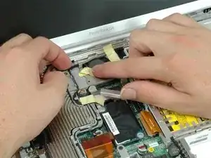
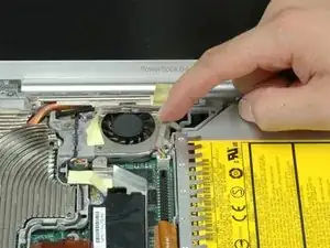
    • Zieh' das gelbe Klebeband ab, mit dem das Wechselrichterkabel in der Nähe des Lüfters befestigt ist.

    FYI, if all you want to do is oil your computer fan, remove the sticker from atop the fan at this step and you will expose three holes that lead directly to the fan's bearing. I used a silicone-based lubricant and sprayed directly into the holes.

    Maecenas -

    many thanks, great tip..

    Jamba -

  18. g3MBQxTXaWgpVHLC
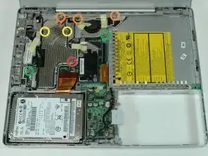
    • Entferne die folgenden acht Schrauben:

    • Eine 4,5 mm Kreuzschlitzschraube in der Nähe des Modems.

    • Drei 6-mm-Kreuzschlitzschrauben in der Nähe des Displays.

    • Zwei große 7,5-mm-Kreuzschlitzschrauben mit Federn.

    • Zwei 13-mm-Kreuzschlitzschrauben - eine unten links am Kühlkörper und eine zwischen Lüfter und dem optischen Laufwerk.

    The middle of the three 6 mm screws (orange circles) is hiding under the cable. Actually you need to do step 24 first, so you can access it.

    jerrykrinock -

    The 6mm screw is mis-labelled on the photo. The actual screw is on the upper-left corner of the frame around the fan, not the one under the heat sink bar across the top.

    Raymond -

    The spring screws here are very hard to remove.. the posts holding them down to the logic board popped off for me, and I wasn't about to remove the logic board to re-solder them. I couldn't even get them apart after they were out though! All I did was re-apply thermal paste to the CPU and thermal pads to the GPU and Northbridge chip, and them put on the heatsink without the two spring screws. It keeps cool temperatures, (118* F after normal web browsing for about an hour), which is pretty good still. Just some reassurement for anyone with the same issue. :)

    Jonas Kvale -

    Yes, these 7.5 mm screws are fussy indeed! The left one came off without issue, the right one spins for days in either direction yet remains tightly secured to the assembly. Not even pliers can loosen the little bugger! Glad to know at least I’m not the only one to encounter this issue.

    Paul Grzelak -

  19. 1N2W22Et3RQniVJy
    • Zieh' das Bluetooth-Kabel auf der rechten Seite des Ventilators ab.

    They say "peel" because it is stuck with adhesive.

    jerrykrinock -

  20. RGZsejCEBlt4NlJU
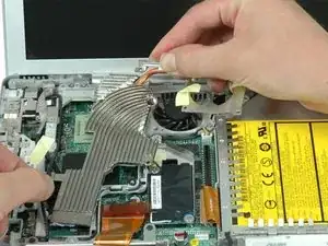
    • Hebe das Wechselrichterkabel mit einer Hand an und lege es vorsichtig um den Kühlkörper. Das Wechselrichterkabel ist noch mit der Hauptplatine verbunden, also pass auf, dass du das Kabel nicht zu stark beanspruchst.

    Not sure what they mean by "thread it around". I would say that you simply lift it up a little so that you'll be able to slide the heat sink assembly out from under it in the next step.

    jerrykrinock -

    How on earth do the 7.5 mm heat sink screws work ? The ones with the springs? I had difficulty taking them out, and now I cant get them back in. They appear to have no threads on them yet all the instructions indicate to remove with a screwdriver. I dont get it-- after working on this for 2 days and I am stuck.

    okiediver -

    Zitat von okiediver:

    How on earth do the 7.5 mm heat sink screws work ? The ones with the springs? I had difficulty taking them out, and now I cant get them back in. They appear to have no threads on them yet all the instructions indicate to remove with a screwdriver. I dont get it-- after working on this for 2 days and I am stuck.

    The screws connect to two posts coming up from the logic board. The post(s) may have popped off the logic board once you removed the screws. If so, you can try super-gluing the posts back to the logic board. There should be one post on either side of the CPU -- see Step 23 to get an idea of how they should look like.

    Miroslav Djuric -

    I had a problem with one of those heatsink screw-posts and the super glue idea hasn't worked...I just left the screw out but when I powered up the computer everything works fine except if I open more than one program the fan kicks on and the computer goes to sleep for a few seconds until I hit the space bar, then everything works great...

    Could this be because the heatsink isn't secure because I didn't put both screws in?

    Robert -

  21. RurBMoBTivtiwyTv
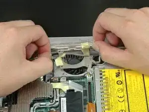
    • Halte den Kühlkörper mit beiden Händen und hebe ihn vorsichtig aus dem Computer. Pass auf, dass du das Kupferrohr, das die beiden Teile des Kühlkörpers verbindet, nicht verbiegst.

    • Wenn du den Kühlkörper wieder in den Laptop einbauen musst, haben wir eine Anleitung für die Wärmeleitpaste, die den Austausch erleichtert.

Abschluss

Um dein Gerät wieder zusammenzubauen, befolge diese Anweisungen in umgekehrter Reihenfolge.

iRobot

Mitglied seit: 25/09/09

0 Reputation

Ein Kommentar

Thank you so much for this wonderful step by step guide! (Though no EMI Finger here neither). By cleaning the terrible mess there was on the microprocessor, and replacing the paste with Artcic Silver, my laptop is 20 C below what it used to be!

wpointw -