Einleitung

Wenn du das obere Gehäuseteil austauschst erhältst du auch ein neues Trackpad. Je nach Ersatzteil kannst du auch beleuchtete Tastaturen verwenden.

  1. cSjY4VwZCbhFeh5r
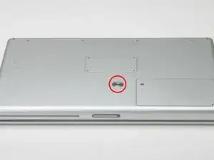
    • Nimm eine Münze und drehe die Schraube am Akkufach um 90 Grad im Uhrzeigersinn.

    • Hebe den Akku aus dem Computer.

  2. cvgou5gisUpXdPoI
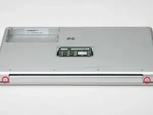
    • Enferne die vier Kreuzschlitzschrauben aus dem Speicherdeckel (RAM).

    • Enferne den Speicherdeckel vom Speicherfach.

    Do you actually need to remove any of the screws on the underneath if you're just replacing a PRAM battery, or a hard drive? Aren't those only required if you're taking the whole logic board out?

    Tom Anderson -

  3. WjURICf5GMXBfdXY
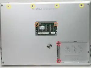
    • Entferne die folgenden 8 Schrauben:

    • Zwei 3mm Kreuzschlitzschrauben im Batteriefach auf beiden Seiten des Batteriekontaktes.

    • Zwei 9mm Kreuzschlitzschrauben auf beiden Seiten des Speicherfachs.

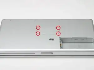
    • Vier 16mm Kreuzschlitzschrauben entlang des Deckel-Scharniers.

  4. NhXgjAkxB2DuiQAY
    • Drehe den Computer um 90 Grad im Uhrzeigersinn, so dass die Netzsteckdose sichtbar ist.

    • Entferne die drei 3mm Kreuzschlitzschrauben.

    • Beim Wiederzusammenbau musst du darauf achten, die drei Schrauben in der richtigen Reihenfolge wieder einzudrehen: Zuerst die Schraube, welche am nächsten zum Monitor-Scharnier liegt, dann die Mittlere und zuletzt die Äusserste.

  5. mU1qZe6FJbnseXae
    • Drehe den Computer um 90 Grad im Uhrzeigersinn, so dass das Monitor-Scharnier sichtbar ist.

    • Entferne die beiden unteren 5mm Kreuzschlitzschrauben auf den Seiten des Monitor-Scharniers.

    The two "bottom" 5mm philips screws here are the ones closest to the display. (as shown in the image)

    seos -

    "Bottom" assumes you have the computer upside down. If you can see the Apple on the front, then remove the two "top" screws...

    Kevin -

  6. KPqtUFIKBUvLYX1k
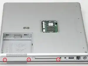
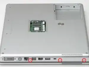
    • Drehe den Computer 90 Grad im Uhrzeigersinn, so dass die Anschluss-Buchsen sichtbar werden.

    • Entferne die drei 3mm Kreuzschlitzschrauben.

    • Beim Wiederzusammenbau musst du darauf achten, die drei Schrauben in der richtigen Reihenfolge wieder einzudrehen: Zuerst die Schraube, die am Nächsten zum Monitor-Scharnier liegt, dann die mittlere und danach die äusserste Schraube.

  7. fSW1Z24IfphoxqAC
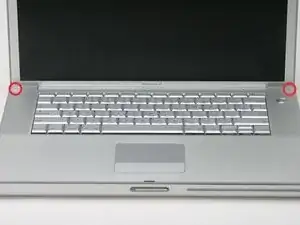
    • Drehe den Computer um und öffne das Display.

    • Entferne die 4.2mm 1/16" H 1,5 Sechskant- Schrauben in den zwei Ecken beim Display (dafür eignet sich am besten ein T6 Torx-Schraubendreher).

    I found that the T6 was too small but a T7 worked, with a little push downward to make it sit inside the hex head.

    dougcabot -

    My T6 worked very well on these 2 screws.

    David Parker -

  8. pFlpx3cwKfiYmwMN
    • Nach diesem Schritt hast du das Schwierigste geschafft. Bald bist du im Inneren des Computers. Atme tief ein und denk an etwas, dass dich glücklich macht.

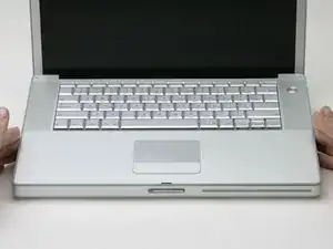
    • Fasse die hinteren Ecken des Gehäusedeckels und hebe ihn an, so dass sich die versteckten Laschen an den Seiten lösen. Ziehe das obere Gehäuse aber noch nicht ab, du musst erst noch die Laschen an der Vorderseite des Gehäuses lösen.

    • Die Nahtstelle ist unter der Plastikleiste des oberen Gehäuses.

    I've opened the G4 four times. The official Apple way outlined above is vastly superior to the paper clip method. When you lower the screen side of the deck, a little bit of pressure toward you will easily release the clips. Definitely begin with the back (screen side) of the deck where you just remove the two T-6 screws.

    wcwirla -

  9. ZhqOaIOAMBkKfDDM
    • Du kannst das obere Gehäuse noch nicht lösen, da es noch eine Verriegelung links vom optischen Laufwerk gibt. Du musst die dünne Metallverriegelung zu dir ziehen und so die Schließe lösen, mit der die Verriegelung fixiert ist.

    • Löse die linke Seite des Gehäusedeckels etwas mit der Hand und schiebe den Kunststoffkeil in die Nahtstelle zwischen Gehäusedeckel und Gehäuse.

    • Belasse den Keil in der Nahtstelle für den nächsten Schritt.

    This could really use a diagram to show exactly how the clip is structured. I didn't realize the clip was between the front of the case and the back support it attaches to, and it needs to be pried off that back support. (Evil Apple design - would it really hurt to have a screw underneath?). Overall these guides are fantastic! I just replaced a hard drive, and it worked great. And I LOVE the screw guide at the back - brilliant idea!

    isonno -

    Apple official disassembly guide suggests instead to lift the upper case from the back up to 45 degrees. Then while lowering it back gently wiggle the upper case and it does disengage the latches. No tools required, no risk of bending the case.

    John -

    This method worked perfectly for me. Lift at 45 degree angle and wiggle as slowly lower and it popped right off.

    th3mamma -

  10. oLUOLwm61kpj3sX1
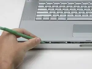
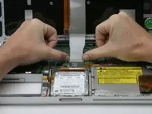
    • Schiebe mit genügend Druck ein Werkzeug in die Naht zwischen den oberen und unteren Gehäusedeckel wie im Bild dargestellt. Es eignen sich ein feiner Haken oder ähnliche Werkzeuge.

    • Den oberen Gehäusedeckel nicht hochreissen, nachdem du die Klammern gelöst hast. Das Gehäuse ist mit zwei Flachbandkabeln am Logic Board befestigt.

    • Schiebe die Spitze des Werkzeuges vorsichtig hinter den silbrigen Metallverschlussriegel, und ziehe ihn nach vorne, während du den Gehäusedeckel hochziehst. Dieser Vorgang verlangt etwas Kraft.

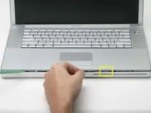
    • Alternativ kann die Schliesse mit einem flachen Schraubendreher durch den CD-Schlitz geöffnet werden. Die Schliesse befindet sich 3 cm links vom Schlitz. Mit dem Schraubendreher wird die Filzblende herausgehoben bzw zurückgedrückt. Ziehe dann den Verschlussriegel (glänzend) mit dem Schraubendreher nach vorne, um ihn von der Klammer (matt) zu lösen.

    I was able to easily release the latch by putting the spudger in the optical drive slot, and gently prying up. You can see the three holes where the upper case clips in above the drive, and the clips are accessible through those holes from the optical drive slot.

    ryan64 -

    "Forward" (step 10) means toward the front. I was not able to release the latch this way. However, I did eventually release all three latches at once by very slightly lifting the rear of the cover and pressing the cover back toward the screen.

    It is not necessary to remove the trackpad and keyboard cables (steps 12, 13, and 14) to replace the hard drive.

    Pomo -

    Zitat von Pomo:

    "Forward" (step 10) means toward the front. I was not able to release the latch this way. However, I did eveIt is not necessary to remove the trackpad and keyboard cables (steps 12, 13, and 14) to replace the hard drive.

    I find it useful to use a big rubber band to hold the keyboard up--put it around the keyboard and display.

    colleenthompson -

    I've done several of these before, but today it was a bear to accomplish. I finally did it by inserting a dental pick through the optical slot and pulling forward to release the clip. In case it will help someone else, pictures of the clip are at Devil Clip.

    colleenthompson -

    I did not find any clip to disengage to remove the top piece. I would like to have seen a picture of the clip after the the top was separated.

    Oh, well. This guide is probably not much use to anyone any more.

    Chrissy -

  11. bHonKwrREyijwfMP
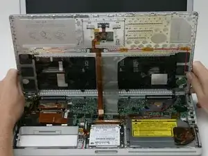
    • Hebe die Rückseite des Gehäuses hoch und gehe mit den Fingern an den Seiten entlang, um das Gehäuse zu öffnen. Wenn die Seiten frei sind, kannst du das Gehäuse auf und ab bewegen, um auch das Vorderteil des Gehäuses zu lösen.

    • Klappe das obere Gehäuseteil nach oben zum Display hin, so dass es dagegen angelehnt bleibt.

    The top assembly for the A1138 model (1.67MHZ high res) does not have two ribbon cables to connect to the logic board as pictured.

    Mike -

  12. V5nEImLmEdjNtMfY
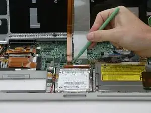
    • Entferne das orangene Klebeband, mit dem das Flachbandkabel zum Trackpad befestigt ist.

    • Trenne das Trackpad-Flachbandkabel vom Logic Board ab.

    If you are just replacing a hard drive, you do not need to remove either the trackpad or the keyboard cables! They will not be in the way at all. Save yourself a headache.

    dougcabot -

    I agree - removing the cables is not necessary. I didn't even have a keyboard cable on my machine.

    macbaen -

    i agree, too:

    steps 12 to 14 are NOT necessary for replacing the harddrive!

    neither are 17 and 18!

    instead:

    after 10 continue with step 15.

    instead of 17 and 18: free the hd carefully

    from the case disconnect the hard drive cable from the hard drive.

    valid -

  13. hBg3NSEtSTq4HSHD
    • Das ist eine Zeichnung des Tastatursteckers, der im nächsten Schritt abgetrennt wird.

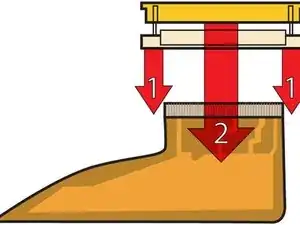
    • 1) Fasse die Sicherungsleiste an jeder Seite mit den Fingernägeln und ziehe sie etwas 2 mm weit heraus.

    • 2) Wenn die Sicherungsleiste geöffnet ist, schiebe das Kabel aus dem Anschluss heraus.

    Be very careful! The clasps holding the black strip are extremely fragile and can snap very easily.

    ChrisT4 -

    Zitat von ChrisT4:

    Be very careful! The clasps holding the black strip are extremely fragile and can snap very easily.

    In fact it is possible to get to your hard drive and replace it without having to detach this ribbon at all and I would advise that if all you are doing is replacing your hard drive then skip this step.

    ChrisT4 -

    My laptop did not have the big gray keyboard ribbon but a short white one with a blue stripe at the end. Anyone knows if this is just a different setup?

    afido -

    my g, 15", 1.5Ghz pbk didn't have this cable at all. It's short white kbd cable attached to the trackpad, and it's orange ribbon cable (only) attached to the logic board as in step 12. lucky me.

    gogreens -

    Yes, the note about skipping this step should be up there, front and center. I followed this step and broke the bit of plastic. Now it's re-fastened with a piece of electrical tape, but I am annoyed because it was totally unnecessary to do that. How do we edit the front page to at least say "OPTIONAL" for this step?

    Focus Fusion Society -

    There should be a note on this to say this step is OPTIONAL. I followed instructions as written, broke the little plastic piece, and have taped it back together with electrical tape. But after replacing the hard drive, I see it was totally unnecessary to take this step. It's a high risk step, people should be warned.

    Focus Fusion Society -

    the diagram is a bit confusing, and the text is a bit confusing for non english speakers. when it said pull up a small amount, i thought you have to try and lift it from the motherboard. all you have to do is move the black plastic bit towards the screen with your fingernails and the broad thing plastic keyboard cable comes off.

    Kiureli -

  14. cqv2OdxSNuuCNS6F
    • Drücke das dünne schwarze Teil an der Sicherungsleiste des Tastaturkabels mit den Fingerspitzen zum Display hin und löse die Leiste ab.

    • Das schwarze Teil ist sehr empfindlich und geht leicht kaputt. Sei sehr vorsichtig, wenn du es vom Hauptteil des Anschlusses abtrennst.

    • Schiebe das graue Display-Flachbandkabel aus dem nun offenen Anschluss heraus.

    • Entferne das obere Gehäuseteil vom Computer.

    My machine didn't have a keyboard ribbon.

    macbaen -

    Watch this step carefully! The release mechanism pushes back slightly, parallel with the surface of the logic board. You may want to gently use a sparger rather than your thumbs if you have big fingers. This is a very delicate connector. Work one side slightly then the other. The good news is that it does not offer any resistance.

    wcwirla -

    I've found, however, that it's not necessary to remove the cables and thus risking breaking these fragile parts. The still-attached keyboard can simply be rested against the screen/lid of the machine while the rest of the work is done.

    Charles Ess -

Abschluss

Um dein Gerät wieder zusammenzubauen, folge den Schritten in umgekehrter Reihenfolge.

iRobot

Mitglied seit: 25/09/09

0 Reputation

0 Kommentare