Einleitung
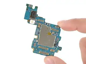
Follow this guide to replace the motherboard (aka main board or logic board) in your Samsung Galaxy S25 Ultra smartphone.
If your Galaxy doesn't power on or randomly shuts down, you may need to replace the motherboard.
Note: You'll need replacement back cover adhesive to complete this repair.
-
-
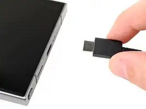
Unplug all cables from your phone.
-
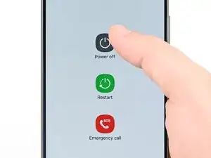
Completely power off your phone by holding the side key and volume down button and selecting Power off.
-
-
-
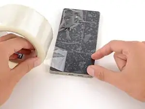
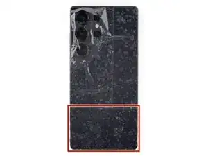
Apply strips of packing tape to the cracked glass until it's completely covered—this will help keep the glass contained and allow the suction cup to stick.
-
Make sure there's a single strip (not overlapping) of tape across the bottom edge, big enough for a suction cup to fit on.
-
-
-
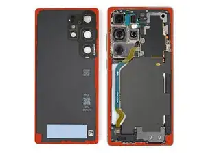
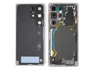
The cover is secured with adhesive around the perimeter of the frame. Use this picture as a reference while you separate the adhesive.
-
-
-
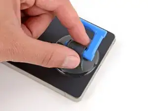
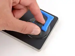
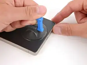
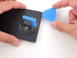
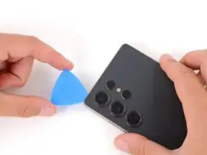
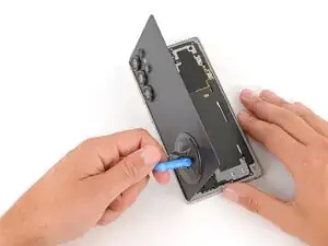
Apply a suction handle to the center of the back cover's bottom edge, as close to the edge as possible.
-
-
-
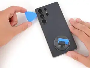
Pull up on the suction handle with strong, steady force until a gap forms between the back glass and frame.
-
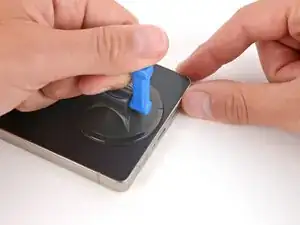
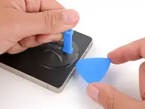
Insert the tip of an opening pick into the gap.
-
-
-
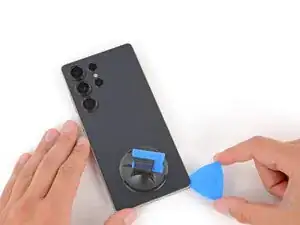
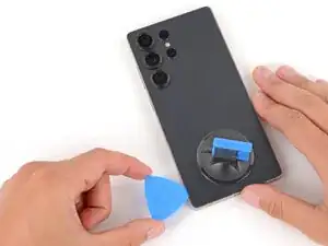
Slide the opening pick around the bottom right corner and up the right edge to separate the adhesive.
-
-
-
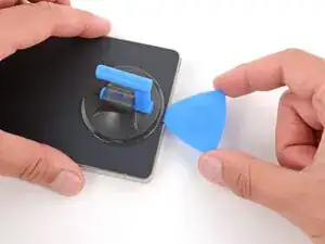
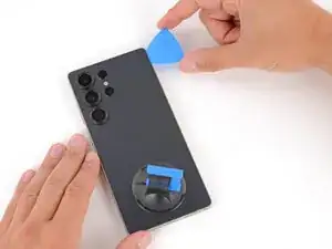
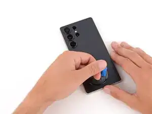
Slide the opening pick around the top right corner and along the top edge to separate the adhesive.
-
-
-
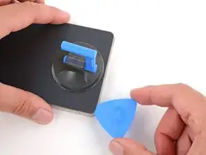
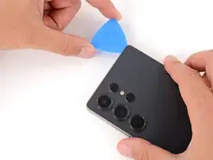
Slide the opening pick around the top left corner and down the left edge to separate the adhesive.
-
-
-
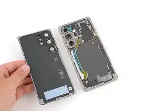
Use the suction handle to lift and remove the back cover.
-
This is a good point to power on your phone and test all functions before sealing it up. Be sure to power your phone back down completely before you continue working.
-
Check your rear cameras for any smudges and gently wipe them with a clean, lint–free cloth if necessary.
-
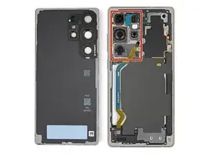
Your replacement back cover adhesive will be applied to either the frame or the back cover. Use cutouts and contours to see where it lines up best. If it matches the back cover, follow this guide. If it matches the frame, use this guide.
-
-
-
Use the point of a spudger to pry up and disconnect the wireless charging coil press connector.
-
-
-
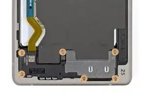
Use a Phillips screwdriver to remove the ten screws securing the wireless charging and loudspeaker assembly:
-
Four 3.5 mm‑long screws securing the wireless charging coil
-
Six 3.5 mm‑long screws securing the loudspeaker
-
-
-
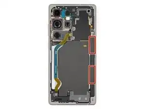
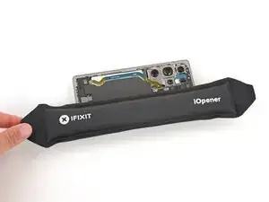
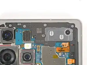
Two tabs on the right side of the wireless charging coil are secured with mild adhesive.
-
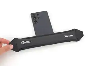
Heat an iOpener and lay it on the tabs for one minute to soften the adhesive.
-
-
-
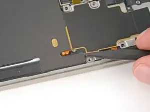
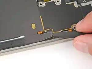
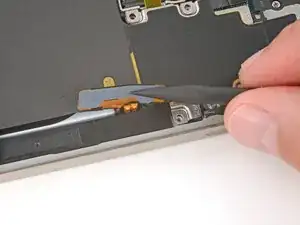
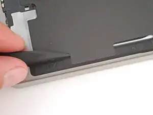
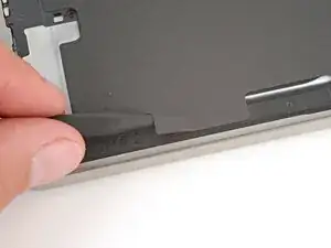
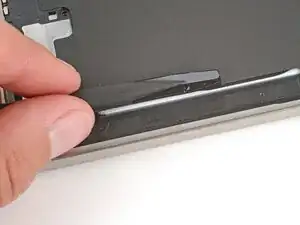
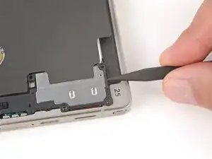
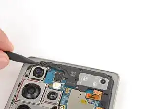
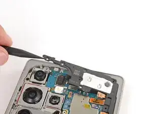
Gently slide the point of a spudger under the top edge of the upper tab and lift slowly to separate it.
-
-
-
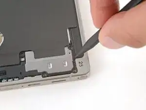
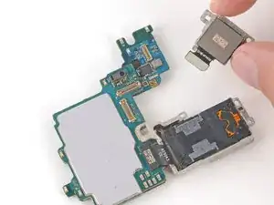
Use the point of a spudger to pry up and disconnect the earpiece speaker press connector (the uppermost, short one) from the top right of the motherboard.
-
-
-
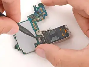
Use a Phillips screwdriver to remove the five 3.5 mm‑long screws securing the earpiece speaker.
-
-
-
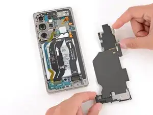
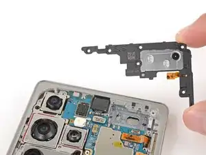
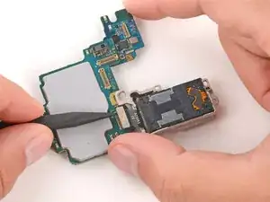
Use the point of a spudger to lift the earpiece speaker by its top left corner until it unclips.
-
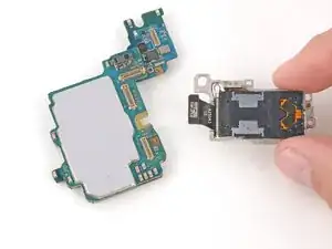
Remove the speaker.
-
-
-
Use the point of a spudger to pry up and disconnect the two press connectors on the USB‑C board's top edge.
-
-
-
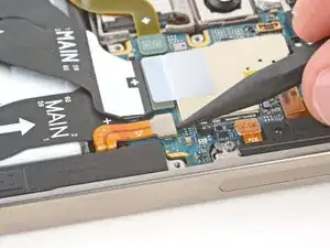
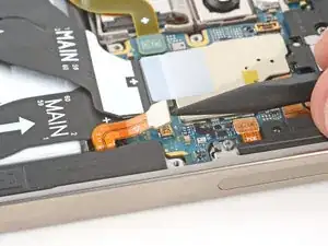
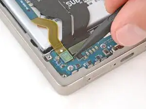
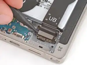
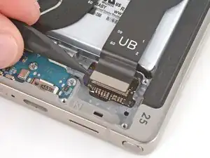
Use the point of a spudger to disconnect the interconnect cable press connector from the bottom right of the phone.
-
-
-
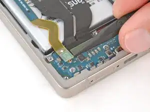
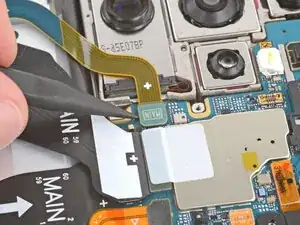
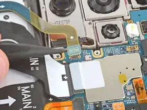
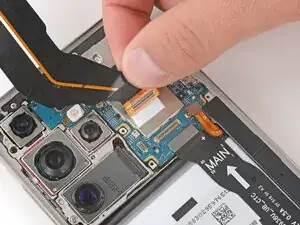
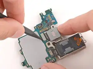
Use the point of a spudger to pry up and disconnect the leftmost (skinny) interconnect cable's press connector from the motherboard.
-
-
-
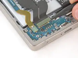
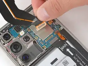
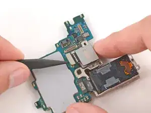
Use the point of a spudger to pry up and disconnect the wide press connector, just to the right of the previous one.
-
-
-
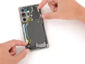
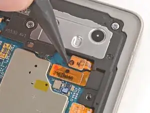
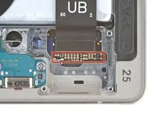
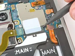
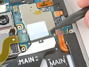
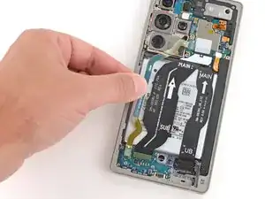
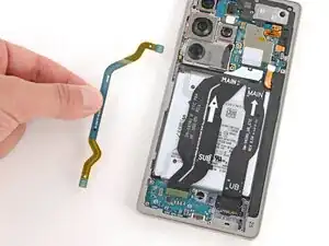
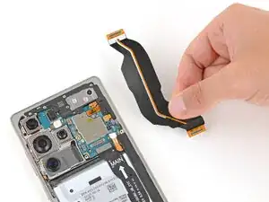
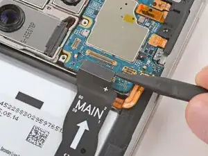
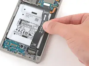
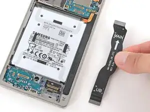
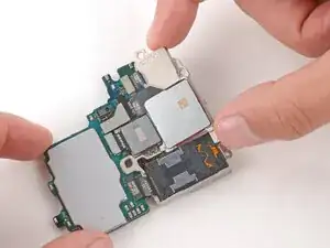
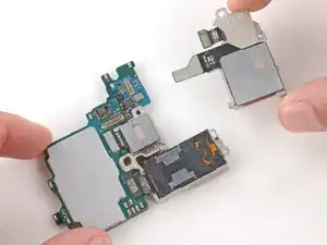
Grip the middle (widest) interconnect cable just above the connector near the motherboard and slowly peel it up and remove it.
-
-
-
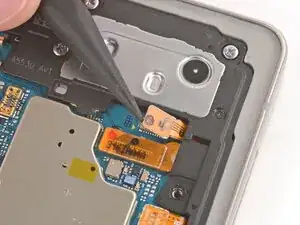
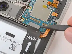
Use the point of a spudger to pry up and disconnect the screen cable press connector from the motherboard.
-
-
-
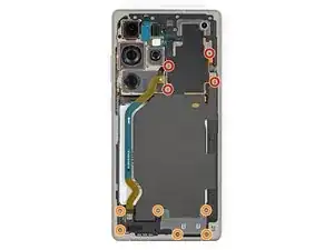
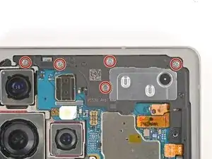
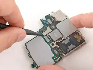
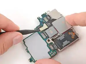
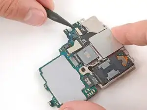
Use the point of a spudger to pry up and disconnect the three remaining press connectors on the top and right edges of the motherboard.
-
-
-
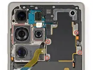
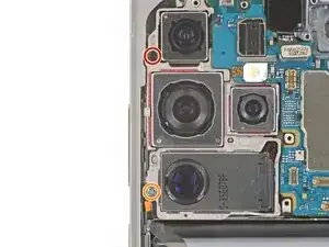
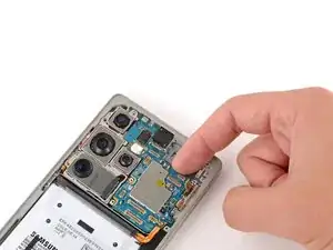
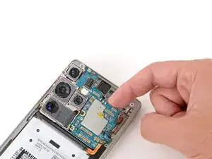
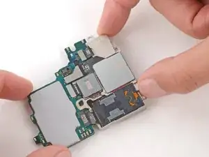
Use a Phillips screwdriver to remove the two screws securing the cameras:
-
One 4.0 mm‑long black screw
-
One 3.5 mm‑long silver screw
-
-
-
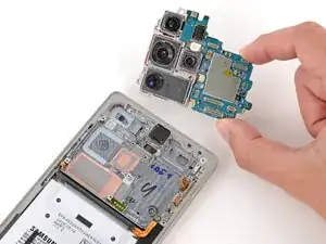
Flip the motherboard over and hold it slightly above your work surface while working on the cameras—don't press the board against your work surface, or you may damage fragile components.
-
-
-
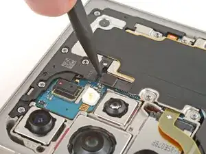
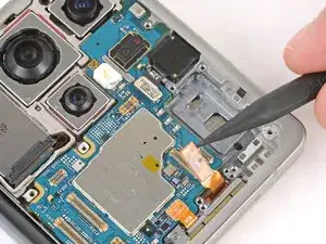
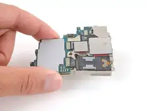
Use the point of a spudger to pry up and disconnect the upper two press connectors for the ultrawide (uppermost) and wide (below) cameras.
-
-
-
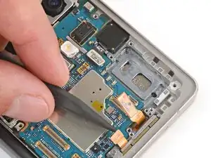
Lift the outer edge of the wide and ultrawide cameras and slide them away from the board to remove them.
-
Slide the cameras into place at a slight downward angle before reconnecting them. Make sure the tab on the top edge goes under the board.
-
Double-check that the cameras are properly slotted together on the bottom and top before continuing.
-
-
-
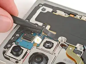
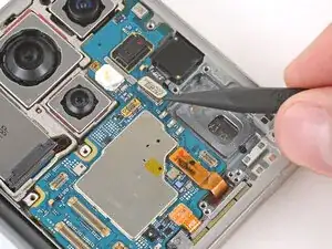
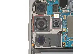
Use the point of a spudger to pry up and disconnect the telephoto (middle) camera press connector.
-
Lift the camera straight up and remove it.
-
-
-
Use the point of a spudger to pry up and disconnect the periscope telephoto (bottom) camera press connector.
-
Remove the camera.
-


Compare your new replacement part to the original part—you may need to transfer remaining components or remove adhesive backings from the new part before you install it.
To reassemble your device, follow these instructions in reverse order.
Take your e-waste to an R2 or e-Stewards certified recycler.
Repair didn’t go as planned? Try some basic troubleshooting, or ask our Answers Community for troubleshooting help.