Einleitung

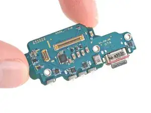
Follow this guide to replace the USB-C board (aka daughterboard or sub board) in your Samsung Galaxy S25 Ultra smartphone.

Before starting this repair, try cleaning the port and see if it fixes your problem.

Note: You'll need replacement back cover adhesive to complete this repair.

Note: The USB-C port and SIM reader are soldered to the daughterboard, so replacing either of these parts requires replacing the entire board.

If your device isn't charging properly, disconnects unexpectedly, or your USB-C cable feels loose when plugged in, you may need to replace the USB-C board.

  1. CXn3vLniFNcqqvI2
    CXn3vLniFNcqqvI2
    y3CxVDvTt1LfgiuI
    • Let your Galaxy's battery drain below 25% before starting this repair—a charged lithium‑ion battery may catch fire if damaged.

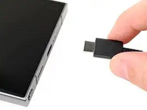
    • Unplug all cables from your phone.

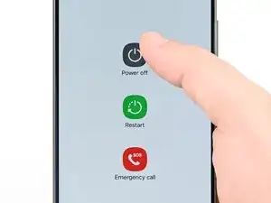
    • Completely power off your phone by holding the side key and volume down button and selecting Power off.

  2. Gm5iiYYcymi1mJqp
    Gm5iiYYcymi1mJqp
    vcQXFMrWI5y1Z365
    6OEQLaV2kbX4cHSs
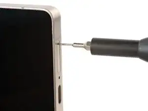
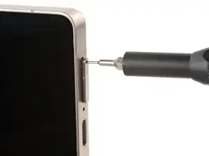
    • Firmly press a SIM eject tool, bit, or straightened paper clip into the SIM card tray hole on the bottom edge of your phone until the tray ejects.

    • A small mic hole is next to the SIM tray—don't confuse the two!

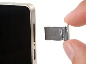
    • Remove the SIM card tray.

  3. tHTuQXOGTeXCyoFO
    tHTuQXOGTeXCyoFO
    ltc4bIKyXpbkPEmv
    VOhDvZrHxqHFFKVM
    • Glass shards can complicate disassembly—or worse, cause injury. If your phone's back glass is cracked, follow this step.

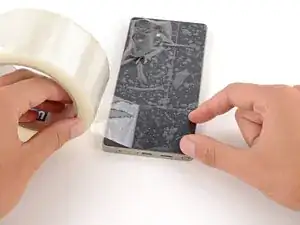
    • Apply strips of packing tape to the cracked glass until it's completely covered—this will help keep the glass contained and allow the suction cup to stick.

    • Make sure there's a single strip (not overlapping) of tape across the bottom edge, big enough for a suction cup to fit on.

    • Only cover the glass itself—don't stick any tape to the frame.

    • Consider wearing safety glasses to protect your eyes from any glass shaken free during the repair.

  4. R1N4dviJAKq2GCRk
    • Adhesive secures the back cover to the frame. Heating the cover softens the adhesive, making it easier to separate.

    • Heat an iOpener and lay it on the bottom edge of the back cover for two minutes.

    • Alternatively, you can use a hair dryer or heat gun to heat the cover.

    • Improper use of a heat gun can destroy the display and/or battery—follow the linked instructions carefully.

  5. M2ljNqn5cDkifxOD
    M2ljNqn5cDkifxOD
    3x16PCxNmhX6LJIy
    wSHHIYNKgFcTniFB
    • While the back cover heats, note the following about its adhesive:

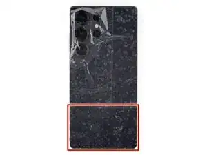
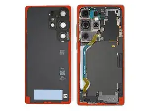
    • The cover is secured with adhesive around the perimeter of the frame. Use this picture as a reference while you separate the adhesive.

    • Only insert your tool slightly under the cover near the cameras to avoid damaging them.

  6. frFaIyFwLPOrpCBY
    frFaIyFwLPOrpCBY
    C1i5hc2qeEgPDqUk
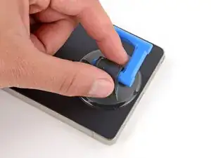
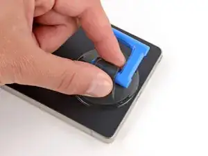
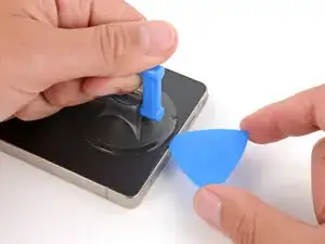
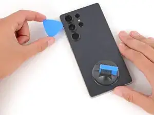
    • Apply a suction handle to the center of the back cover's bottom edge, as close to the edge as possible.

  7. SbUASkqSFgNJoOYq
    SbUASkqSFgNJoOYq
    VN2UpXxKTZXR2wQs
    4sjNjTwXaf6xmoQq
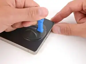
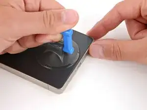
    • Pull up on the suction handle with strong, steady force until a gap forms between the back glass and frame.

    • Use the fingers of your lifting hand to hold the phone down, or steady the frame with your free hand—be careful, your phone may be hot.

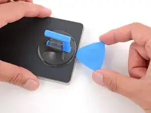
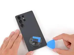
    • Insert the tip of an opening pick into the gap.

  8. IG5VRDHDnQel1jSe
    IG5VRDHDnQel1jSe
    yqntxjrB3ILolaId
    bDXJfCCQsIOxRKWO
    • If the back cover feels stuck at any point when separating the adhesive, apply heat to the area and try again.

    • Slide the opening pick along the bottom edge to separate the adhesive.

  9. xJMIQuHuAxcrkKla
    xJMIQuHuAxcrkKla
    lO3JsEfUTbNifnS4
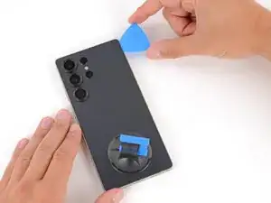
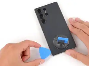
    • Slide the opening pick around the bottom right corner and up the right edge to separate the adhesive.

  10. ZiLxosKYCGEFR2wN
    ZiLxosKYCGEFR2wN
    xlvRIIaBXOW3lvEW
    • In the next two steps, only insert the pick slightly (a few millimeters) near the cameras to avoid damaging them.

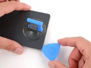
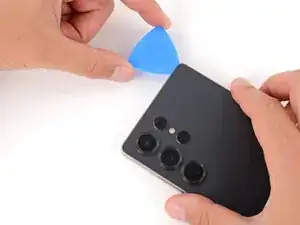
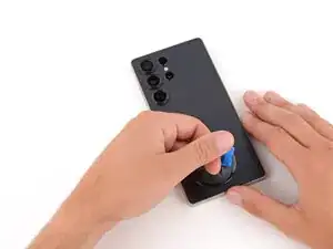
    • Slide the opening pick around the top right corner and along the top edge to separate the adhesive.

  11. dG6wseFJ4WpZUDGC
    dG6wseFJ4WpZUDGC
    vEqEwYqOmSBII4mr
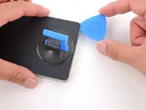
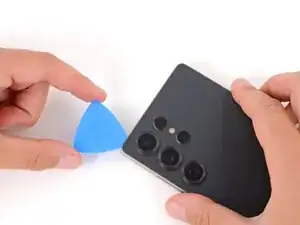
    • Slide the opening pick around the top left corner and down the left edge to separate the adhesive.

  12. dKwPuiQvFNETBAvu
    dKwPuiQvFNETBAvu
    SFHypxAoIYXVDJEW
    yWZaUc2RO5Uj4DCQ
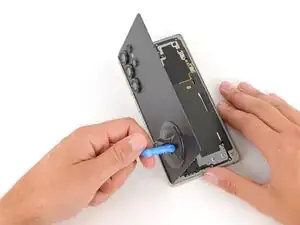
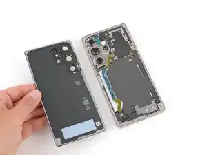
    • Use the suction handle to lift and remove the back cover.

    • If the cover still feels stuck, go back around the perimeter with an opening pick and separate any remaining adhesive.

    • During reassembly:

    • This is a good point to power on your phone and test all functions before sealing it up. Be sure to power your phone back down completely before you continue working.

    • Check your rear cameras for any smudges and gently wipe them with a clean, lint–free cloth if necessary.

    • Your replacement back cover adhesive will be applied to either the frame or the back cover. Use cutouts and contours to see where it lines up best. If it matches the back cover, follow this guide. If it matches the frame, use this guide.

  13. meDUdiEqY3YYOKC5
    meDUdiEqY3YYOKC5
    oL4rVsvUOtSqLRsZ
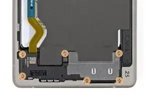
    • Use the point of a spudger to pry up and disconnect the wireless charging coil press connector.

  14. SjSHlBpAr6sbAg4H
    SjSHlBpAr6sbAg4H
    iSXlVQYRWKoXKYtE
    TDfQrTEEpIJs4spp
    • Throughout this repair, keep track of each screw and make sure it goes back exactly where it came from to avoid damaging your phone.

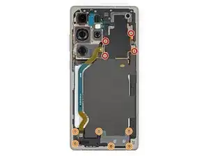
    • Use a Phillips screwdriver to remove the ten screws securing the wireless charging and loudspeaker assembly:

    • Four 3.5 mm‑long screws securing the wireless charging coil

    • Six 3.5 mm‑long screws securing the loudspeaker

  15. idWOdeBmusgPfBve
    idWOdeBmusgPfBve
    wUTCGMgUCpxOXASv
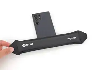
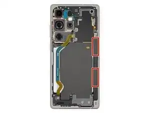
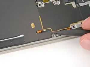
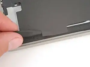
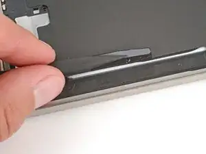
    • Two tabs on the right side of the wireless charging coil are secured with mild adhesive.

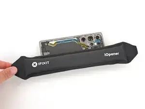
    • Heat an iOpener and lay it on the tabs for one minute to soften the adhesive.

  16. 6NkYlgiVxTvkGOLD
    6NkYlgiVxTvkGOLD
    13xkKD5ZltMlhp6j
    XJCcWAA1Y6KM2Lps
    • During the next two steps, be very careful not to puncture or dent the battery, as it can leak dangerous chemicals or catch fire. Don’t use sharp or metal tools.

    • The tabs are very fragile. If it feels like they may tear, apply more heat and try again.

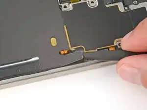
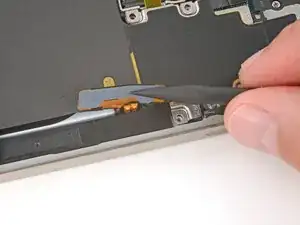
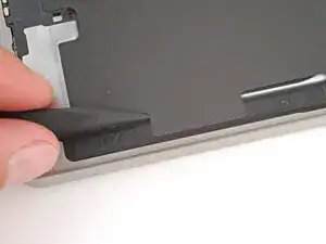
    • Gently slide the point of a spudger under the top edge of the upper tab and lift slowly to separate it.

    • You may need to do this a few times before the tab fully separates.

  17. AS4aQpyJ4oK4yLnP
    AS4aQpyJ4oK4yLnP
    lbTtnUkwbdVhiLmv
    ejSlLWuByqGoia4H
    • Repeat the previous step to separate the lower tab, starting at the bottom edge.

  18. RDCTMXuucHphZbTY
    RDCTMXuucHphZbTY
    BDEvhB5UveN6uoqp
    • Use the point of a spudger to pry up the right side of the loudspeaker and unclip it.

    • During reassembly, press firmly around the perimeter of the loudspeaker to engage its clips.

  19. cByFHV3pWBsYHQda
    cByFHV3pWBsYHQda
    IjNC5ZF1JCXkfP1y
    • Use two hands to remove the wireless charging and loudspeaker assembly.

  20. rLyMEklmaSeDaq5U
    rLyMEklmaSeDaq5U
    oIEeGFeorMYnHbVl
    • Every press connector has a corresponding gold arrow on the board that shows the proper location to pry—nifty! Prying at the wrong location risks damaging the fragile surface‑mounted components on the board.

    • Use the point of a spudger to pry up and disconnect the battery press connector.

  21. UbNR4qQMMGKHTIeK
    UbNR4qQMMGKHTIeK
    GEgivYCRZLwUFVy3
    2GQ3Jh2UTt3gu5ZI
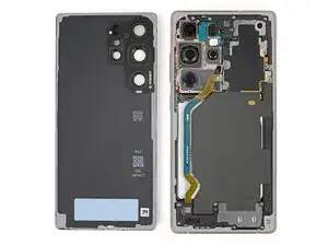
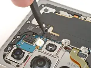
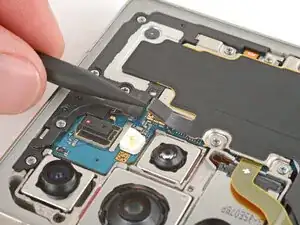
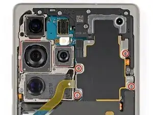
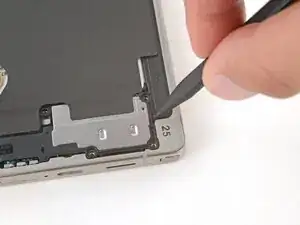
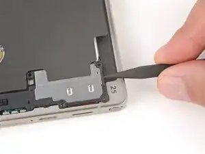
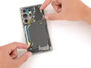
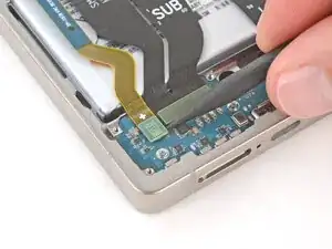
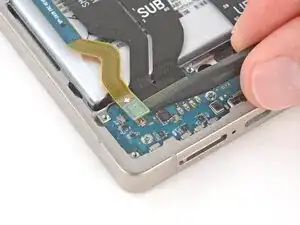
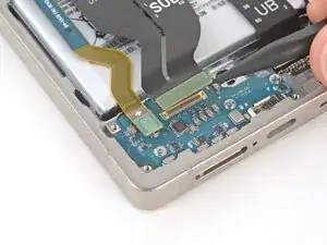
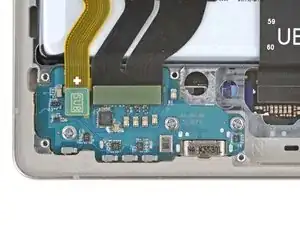
    • Use the point of a spudger to pry up and disconnect the two press connectors on the USB‑C board's top edge.

  22. 4XAWjZShgwtSmnYf
    4XAWjZShgwtSmnYf
    6lCihvYARiDN3BWU
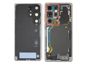
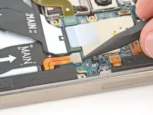
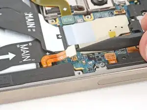
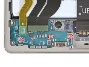
    • Use a Phillips screwdriver to remove the three 3.4 mm‑long screws securing the USB-C board.

  23. TDqfBygcgPkVHppW
    TDqfBygcgPkVHppW
    c1erBVhUQsXgFQNS
    eipiXD4mNGV11QJt
    • Before trying to remove the board, make sure you've removed the SIM card tray.

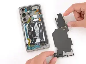
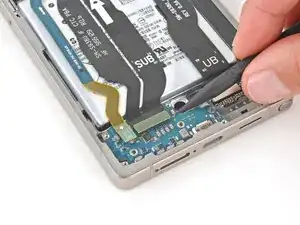
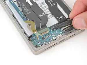
    • Insert the point of a spudger in the gap under the top right corner of the USB-C board and gently lift until it unclips.

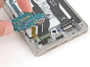
    • Remove the board, making sure the cables don't get snagged.

    • During reassembly:

    • Make sure both cables that connect to the USB‑C board are out of the way—you may need to hold them up as you insert the board.

    • Insert the USB‑C board at a slight downward angle, guiding the port into its recess. Make sure the push connectors on the bottom edge are properly seated against the frame.

    • With the board in place, press down firmly on the center of the top edge to clip the board in place.

    • Be careful not to press on any small, surface‑mounted components.

Abschluss

Compare your new replacement part to the original part—you may need to transfer remaining components or remove adhesive backings from the new part before you install it.

To reassemble your device, follow these instructions in reverse order.

Take your e-waste to an R2 or e-Stewards certified recycler.

Repair didn’t go as planned? Try some basic troubleshooting, or ask our Answers Community for troubleshooting help.

Spencer Day

Mitglied seit: 14/09/22

170336 Reputation

0 Kommentare