Einleitung

  1. gPXCbtYRX6jtLsDD
    • Trenne die Stromversorgung ab und warte ein paar Minuten, bis die Kondensatoren entladen sind.

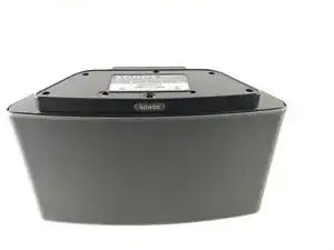
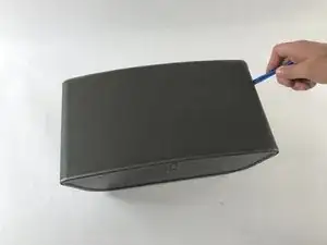
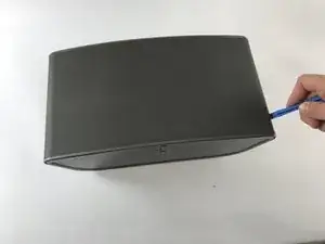
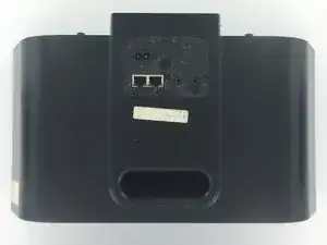
    • Drehe den Lautsprecher um, so dass die Unterseite nach oben zeigt.

    • Es kann sein, dass die Schrauben auf der Unterseite durch Gummifüße verdeckt sind Ziehe sie mit Hilfe eines Spudgers ab. (Im Bild nicht gezeigt).

    By the time you actually reached the motherboard the capacitors will already be discharged sufficiently to a safe level, so just go ahead there's no need to wait in this step.

    That said, be careful once you have the motherboard out and decide to test it on your table. The two large capacitors are directly behind the full bridge rectifier that's connected to the mains, so without load they carry the peak voltage. In Europe with 230V that means 325V, in 110V countries that means 156V (see https://en.wikipedia.org/wiki/Alternatin... for more information about RMS and peak voltages).

    Erik Mouw -

  2. ssEZ5tToZG3Moihr
    ssEZ5tToZG3Moihr
    jZqJUyInUQGmxQuJ
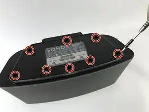
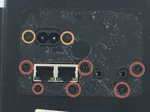
    • Entferne acht 10 mm lange Kreuzschlitzschrauben #2.

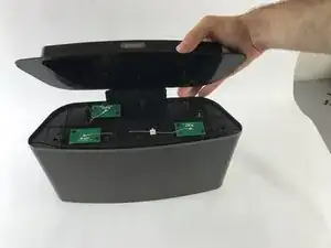
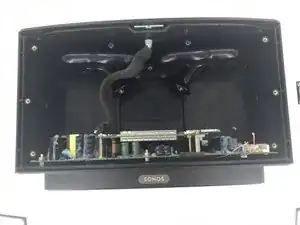
    • Ziehe die Bodenplatte nach oben und entferne sie.

    • Sei besonders vorsichtig an den Enden der drei Antennen, sie sind sehr empfindlich.

    NB: in the photograph, two antennas of the three soldered on the antenna PCBs are broken: You can see one standing upside down towards the center-right of the photograph

    Toni -

    On my model, only 6 of the 8 screws hold the bottom panel. Looking at the picture above, where the screws are circles, the bottom row of 5 screws, the second and fourth screw are threaded for nuts, as opposed to the other six, which are threaded for plastics. These two screws can be removed once the bottom panel has been removed.

    Toni -

    Like the previous poster said: in this step it is sufficient to remove the second and fourth screw cause these hold the front panel. Removing the front panel takes a bit of force and it is better to have the fragile WiFi antennas protected by the bottom panel.

    The remaining six screws can be removed just before step 13 (which also misses a step, see my comments over there).

    Erik Mouw -

  3. STWtAoFNiinNbhup
    STWtAoFNiinNbhup
    tX1HXstZLJtGl1On
    rbFRqxBkFDbVaZnN
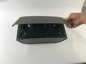
    • Lege den Lautsprecher so, dass der Lautsprechergrill oben ist.

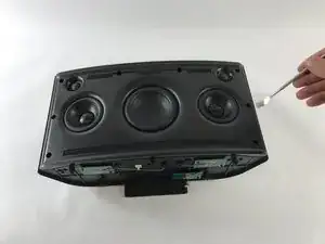
    • Finde die Naht zwischen Grill und Kunststoffgehäuse an der rechten Seite. Setze ein Öffnungswerkzeug aus Kunststoff in diesen Spalt ein.

    • Lasse das Werkzeug im Spalt entlang laufen, um den Grill zu lösen. Verfahre genauso auf der linken Seite.

    • Ziehe den Grill vorsichtig ab und entferne ihn.

    might be worth mentioning there are two strips of industrial velcro running along near the top and bottom that simply have to be pulled apart

    Adam Tibbalds -

    Run the plastic opening tool under the grille to remove to pull the velcro apart. In that way you avoid bending the grille. Be careful with the speaker cones, though.

    Erik Mouw -

  4. KUcjokm6wtXCLifZ
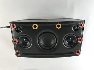
    • Entferne sechs 8 mm lange Kreuzschlitzschrauben #2.

    • Entferne zwei 10 mm lange Kreuzschlitzschrauben #2.

    In my unit the top two screws marked in red had a rubber plug in the hole as well. I had to remove them by sticking a knife in and carefully pulling them out.

    Adam Tibbalds -

    I had the same issue but no problem getting them out.

    clarkal2000 -

    I pulled them out using the corkscrew method: I drove a screw about 10mm deep into the rubber plug, then pulled up the screw. This method created way less damage than other methods i have tried.

    Toni -

  5. cLVG4SfPrbcrXUjo
    cLVG4SfPrbcrXUjo
    JnIQdCgHvKhtcOVd
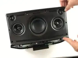
    • Finde die Naht zwischen Vorderfront und Rückseite an der rechten Seite. Setze ein Öffnungswerkzeug aus Kunststoff in diesen Spalt ein. Lasse das Werkzeug im Spalt entlang laufen. Verfahre genauso auf der linken Seite.

    • Hebe die Vorderfront mit dem Öffnungswerkzeug hoch. Wenn das Kunststoffwerkzeug nicht ausreicht, verwende (vorsichtig) eines aus Metall.

    • Ziehe vorsichtig an der Vorderseite nach oben um nachzuprüfen, ob sie wirklich komplett abgelöst ist.

    • Sei vorsichtig, die Vorderfront ist immer noch auf ihrer Rückseite mit Kabeln angeschlossen.

  6. GMOtKHefETYH4XLC
    GMOtKHefETYH4XLC
    pUJgkNe2yMRKO6TY
    fZbdDKnQrUrLDVmH
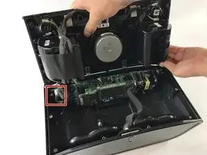
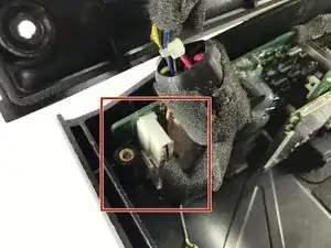
    • Hebe die Vorderfront an und Stelle sie rechtwinklig zur Rückseite. Finde den im Bild gezeigten Stecker mit zehn Kontakten. Dieser Stecker verbindet die Vorderfront mit der Rückseite.

    • Drücke die kleine Sperre am Stecker herunter und halte sie gedrückt. Ziehe den Stecker aus dem Anschluss heraus.

    • Nun ist die Vorderfront ganz abgetrennt und du kannst sie entfernen.

    my unit didn’t have the tab in the middle of the connector. It simply had to be prised apart (I used a plastic spudger to separate the two parts of the connector) and then reconnected carefully (I used the plastic spudger again between the pcb and the case to support the pcb as it was flexing)

    Adam Tibbalds -

    My unit has a white gasket between the front and back panel. It was stuck to the front panel when I opened the unit. When rebuilding the unit it was easier to remove the gasket and put it in the small ridge of the back panel.

    Erik Mouw -

  7. KRoQCCKAkG2UubJw
    KRoQCCKAkG2UubJw
    3RW6pcFIXsOeCcJ1
    cfNRNQrLAkRLLPMC
    • Ziehe den Stecker mit den zehn Kontakten ab.

  8. itP6CngpnPOoPNux
    • Lege das Gerät auf der Vorderseite ab.

  9. vVsLYIrWOsNduuJs
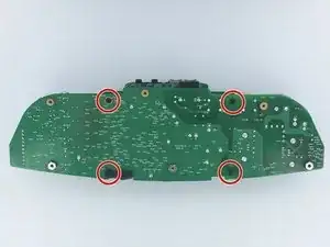
    • Entferne sechs 5 mm lange Kreuzschlitzschrauben #0

    • Entferne zwei 7 mm lange Kreuzschlitzschrauben #2.

  10. RMoxyVQhYrIA5GnZ
    • Lege das Gerät auf seiner Rückseite ab.

  11. nsKWXFoGXFEjaRCY
    nsKWXFoGXFEjaRCY
    OFAFSfWCX6G2sAOK
    tGv5cVpVEMjjWxjG
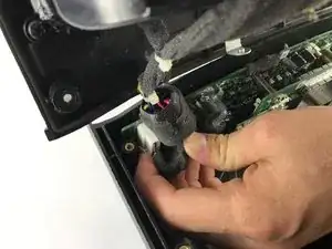
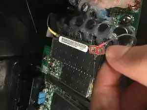
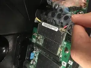
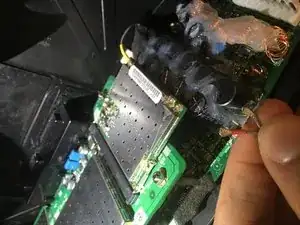
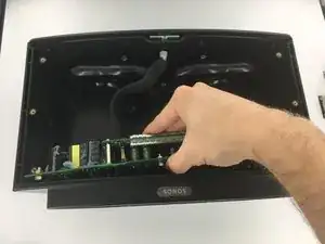
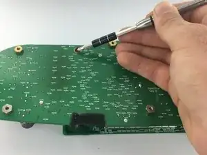
    • Hebe den grauen und den roten Antennenstecker von der Platine hoch und trenne sie ab.

    • Entferne die Kabel von der Platine.

    Hi! Great guide. These three cords have been ripped away on my second-hand-unit. Where do they connect?

    Thanks again!

    Martin Lindström -

    Instead of these following steps, I unsrewed the 4 nuts, lifted the controlboard up, and kept the antennas connected, then I could remove the Powerboard with antenna connections intact…

    Flera Brev -

    The antenna connectors were hidden on blobs of yelliow glue, so I did the same as previous poster: unscrew the four nuts and lift the controlboard out instead.

    Erik Mouw -

    Hi,

    Because the connectors were glued I broke one of the connector from the board. Is that fixable? If I connect directly to the internet with a cable, do I need the antenna? Thanks

    maartenvlug -

  12. fCnyCrgjdkL5JmSt
    fCnyCrgjdkL5JmSt
    vC4V2E51X3yypxUD
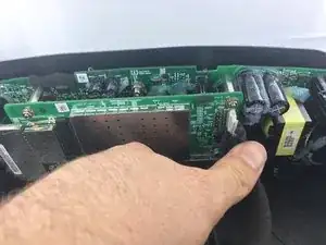
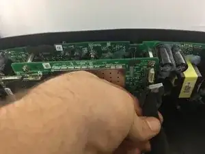
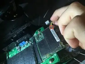
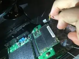
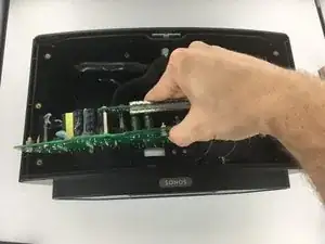
    • Hebe den gelben Antennenstecker von der Platine hoch und trenne ihn ab.

    • Entferne das Kabel von der Platine.

  13. eNCCH4WPrdagdY5O
    eNCCH4WPrdagdY5O
    S4XI4goPdKn1K6BS
    nJ3LxtguRFlJkxXf
    • Hebe die Platine gerade von der Rückseite ab und entferne sie.

    One step is missing…you also have to disconnect the cable to the top circuit board with the volume buttons and led…

    Flera Brev -

    Are you referring to the 10 pin connector in Step "Motherboard"?

    Toni -

    On my model, the motherboard is held in place with another six (i think) screws which go in the steel posts that support the motherboard. This step is completely missing in this guide. Interestingly enough, in the bottom panel removal step, the photograph does not show the screws, as if somebody had removed them: i honestly don't think that in any revision Sonos would leave the motherboard secured only by the screws on the back, where the connectors are, because the motherboard would rattle with music.

    Toni -

    What previous poster said, and in line with my remarks at step 2: there is a missing step. The motherboard is screwed to the bottom with six screws. You have to remove these screws before you can take out the motherboard.

    Erik Mouw -

  14. qEtMld11SbGyFhJJ
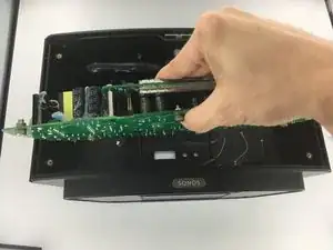
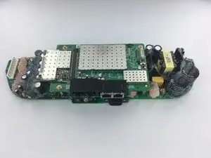
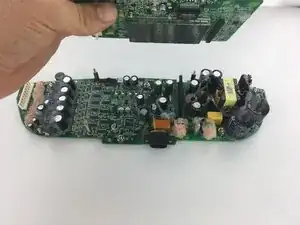
    • Lege die beiden miteinander verbundenen Platinen so, dass die Stromversorgungsplatine nach oben zeigt.

  15. 2clSgGuBhYDftmBZ
    2clSgGuBhYDftmBZ
    broOjcwiFItb2KHP
    • Drehe die vier Kreuzschlitzschrauben #2 soweit wie möglich heraus.

    • Diese Schrauben werden sich zwar nicht entfernen lassen, aber lösen sich trotzdem aus den Schraubenmuttern auf der anderen Seite der Platine.

  16. OBk6fgsWSkUeMBOW
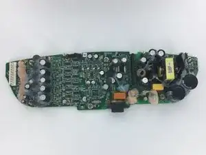
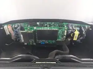
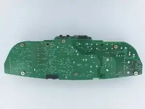
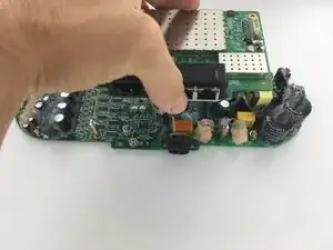
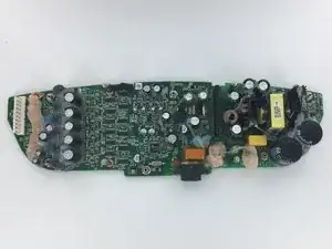
    • Lege die Platinen wie auf dem Bild zu sehen so hin, dass die Audioplatine nach oben zeigt

  17. vCrfPQCLJmDoxYWZ
    vCrfPQCLJmDoxYWZ
    XEswFFBXKwefhffX
    SilkYyTpnaxBanGU
    • Hebe die Kontrollplatine nach oben von der Stromversorgungsplatine weg.

  18. C5QcGMEIJwmOn2hs
    • Die größere der beiden Platinen ist die Stromversorgungsplatine.

    mine was destroyed by a spike in line voltage 380V instead of normal 240V. Have you any idea which part/fuse could I try to replace? I suspect it is only a power supply board problem

    suma -

    The small brownish round part left behind and very close to the (black) powerplug connector is a 3.15A 250V PCB mount fuse.

    Mine was blown.

    Replaced it with a new one (eBay 6 of them for just $2) and my Sonos works again!

    Eric -

    Told a friend I repaired my Play5 when I said he had one which didn’t do anything anymore fo quite a while.

    Sure enough the PCB mounted fuse was dead.

    Checked the bridge rectifier first before replacing the fuse and it turned out that 1 of the diodes was conducting in both directions..

    Told him there was chance that the circuitry behind it was killed by the AC voltage.

    After removing the bridge rectifier I put 30V DC on the circuit with a power supply on which I can limit the current.

    Hardly any current so I assumed that at least the circuitry behind the bridge rectifier did not cause a short circuit.

    Eric -

    To replace the bridge rectifier I first had to remove the 100uF 400V capacitor.

    As they put a kind of silicone on the power supply part of the PCB this wasn’t easy…

    During removal of the bridge rectifier I slightly damaged the connection between the + side of the bridge rectifier and the PCB.

    I ended up by connecting the + side of the bridge rectifier with the + side of the other capacitor (next to J27706 on the backside of the board).

    Replaced the fuse, connected the board to the mains and the fuse did not blow.

    Reassembled the Play5 et voila, it works again!

    I do not understand why they don’t use a separate power supply board!

    Eric -

    Hi! Do you have the model of the rectifier diod and the fuse you ordered? I have the same problem!

    Flera Brev -

    OK, I see the fuse, but what is and where is the “bridge rectifier?” I am supposing that it should conduct in only one direction, and that it has to be off the board to test. Is any of this correct?

    Paul -

Abschluss

Um dein Gerät wieder zusammenzubauen musst du die Anweisungen in umgekehrter Reihenfolge befolgen.

Warren Willingham

Mitglied seit: 20/02/17

1104 Reputation

9 Kommentare

Great guide but where can you get replacement boards from, if at all?

Mark Molloy -

Yes good question, where to get a replacement board SONOS P/N: 170-00236?

Model: JB Power Board

B. Buil -

Does anyone know the specs on the five electrolytic capacitors that are arranged vertically (on the left side of the last image above)? I have a couple failing on one board, and I think that’s what is causing the amp to ‘click’ once it warms up.

T C -

We replaced the parts listed in the description of this clip, and the unit came back to life: https://www.youtube.com/watch?v=2R8hKdGT...

The procedure is a bit unclear in the clip, suggest following the ifixit-procedure, or both.

Roger Bratseth -

Thank you for your work here. Youtube video also useful.

I needed to purchase quality solder iron plus tips, solder wick, and review how to desolder capacitors. Taking out the bad fuse and the rectifier were relatively easy, but the capacitors were covered in silicone, then the old solder on its terminals proved very difficult to melt. In the end, even with temperature of tip at 340, little progress was made, so I disassembled capacitor in situ, and finally with more heat the remnant of it and the two terminals popped out. Again ,I saw this technique on YouTube.

So, having had a live chat with sonos who told me I had no warranty and it was unfixable, and that the new sonos5 is not compatible with my current Generation 1 system, I got the thing working, with next to no initial knowledge.

Cost

£90 in tools- solder iron, tips, quality electronic pliers

£10 in components from Farnell

And about 6 hours disassemble, doing the biz ( the learning curve of desoldering, removing caps, fuse, rectifier) then reassembling

Gordon Mckenna -

Trying to fix a board for play 5 which is flashing white any suggestions?

Tibor -

Just to add a “me too” comment. My problem was that the bridge rectifier had shorted, which had, in turn blown the red cylindrical fuse.

To test whether your bridge rectifier is duff, use a multimeter to check continuity between any and all of its 4 legs. There should be none at all, mine was beeping when I bridged two of the legs.

I had to remove the big capacitor in front of the rectifier in order to access it, but that was no problem (just make sure you put it back in the right way round).

About £1.50 worth of parts to save £350 on an “upgraded” unit from Sonos. It helped that I already had a soldering iron.

C Wheatland -

I followed this guide and the Youtube video. It turned out the cause of the failure in my unit was a real life bug. Somehow a mosquito managed to get into the unit through one of the bass reflex ports (see pictures in step 10) and cause a short between two pins in the connector that connects the audio board to the motherboard. After cleaning up and reassembly the unit came back to life.

Erik Mouw -

I cannot see well enough to make these repairs myself on my Play 5 Gen 1. Is there anyone out there that offers repairs on these units? Thank you!

Randy -