Einleitung

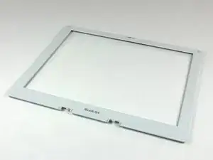
Diese Anleitung zeigt, wie eine defekte Frontblende des Displays ausgetauscht werden kann.

  1. hrdON2aDSgeNeU2G
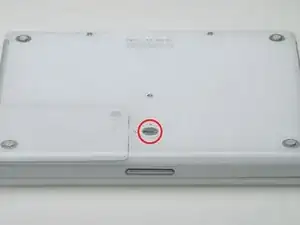
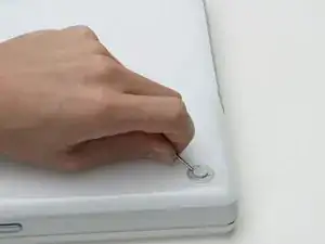
    • Drehe die Verschlussschraube des Akkufachs mit einer Münze um 90° im Uhrzeigersinn.

    • Hebe den Akku aus dem Computer.

    Also unplug the computer just before taking the two steps described above.

    Ken Horner -

  2. GqEIY2mvi2vNjt5R
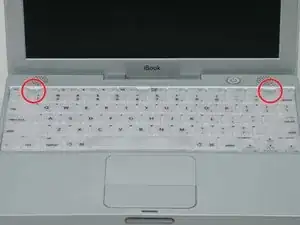
    • Ziehe die Laschen, mit denen die Tastatur eingeklinkt ist, zu dir, bis sich die Tastatur löst.

    • Wenn sich die Tastatur doch nicht ablöst, dann drehe die Befestigungsschraube der Tastatur mit einem kleinen Flachschraubendreher um 180° in die andere Richtung und probiere es erneut.

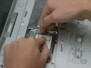
    • Klappe die Tastatur vom Display weg und lege sie mit den Tasten nach unten auf das Trackpad.

  3. VgYRDtkiJKRfdBZb
    • Wenn der Computer keine AirPort-Karte eingebaut hat, dann überspringe die nächsten beiden Schritte.

    • Drücke die Kabelklammer zur AirPort-Karte hin und ziehe sie von der RAM-Abschirmung weg.

  4. 4tCKyYIWuFYHvGSQ
    • Fasse die durchsichtige Kunstofflasche an der AirPort-Karte an und ziehe sie nach rechts.

  5. ZE6VOFOMDHaPeBIo
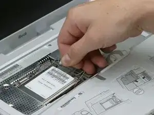
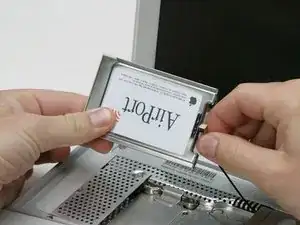
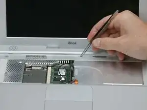
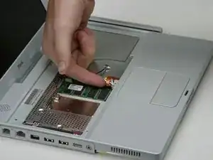
    • Halte die AirPort-Karte mit einer Hand fest und entferne das Antennenkabel mit der anderen Hand.

  6. YoOiVLGWhMFqtHmJ
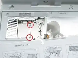
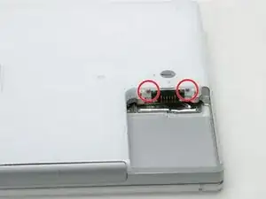
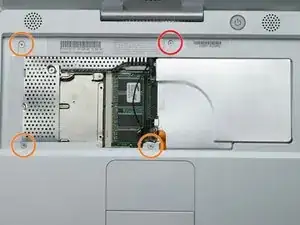
    • Entferne die beiden 2,5 mm Kreuzschlitzschrauben, mit denen die RAM-Abschirmung befestigt ist.

  7. btXyfarCcSu1n2MR
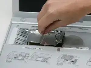
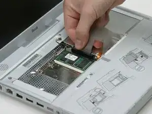
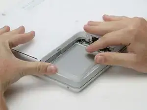
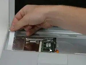
    • Fasse die Metallhalterung oben auf der RAM-Abschirmung und ziehe sie hoch, bis sich die Abschirmung ablöst.

  8. P3BBuGpqdLN31QUE
    • Fasse das Tastaturkabel so nahe wie möglich am Stecker und ziehe es vom Logic Board ab.

    Note: The cable may have adhesive holding it to a shield. Pull in an upward direction gently, with an evenly distributed force across the cable until it comes loose from the shield.

    gsp -

    I feel this step needs clarification: Are just lifting the cable away from the shield, or are we removing the cable entirely?

    David Maag -

  9. TAshvQ6ofQr66abp
    • So ungefähr sollte dein Laptop aussehen.

    Don’t we need to remove the screws before the next step?

    David -

    Remove the two long screws along the back edge, and the shorter screw in the middle. Torx T-8. Pry up the rubber feet, and unscrew the three Phillips screws that hold the feet in place. Putting the silver collars back requires a little bit of fiddling to get them oriented correctly so they sit flush with the bottom case.

    Robin Ray -

    Step 10 should come after step 15.

    Robin Ray -

  10. YPApTHnrHf5XuLo5
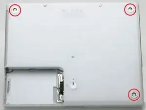
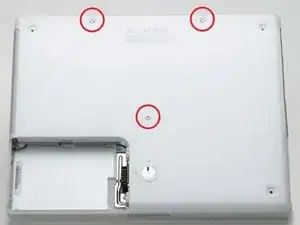
    • Entferne die drei Gummifüße mit einer Nadel (oder einem anderen spitzen Werkzeug) vom unteren Gehäuse.

  11. jp2cyAVPdd4NU4st
    • Entferne die jetzt freigelegten drei 5,2 mm Kreuzschlitzschrauben.

    Screw sizes are 2.5mm x 6mm flat low profile head or cheese head.

    Xnriq -

    this should be after step 12 no?

    panakabear -

    This should be step 3.

    Ken Horner -

  12. FcMBBGQMOfyHQTjP
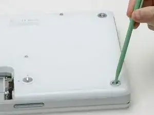
    • Entferne die drei Metallringe, mit denen die Gummifüße eingefasst waren, mit einem Spudger oder einem kleinen Flachschraubendreher.

  13. T5fFqxZCPhLYpPdM
    • Entferne die eine 10 mm und die beiden 20 mm Schrauben mit einem 2 mm Sechskantschlüssel. Du kannst auch einen Torx T8 Schraubendreher benutzen.

    FYI, the two screws at the top of this picture are longer than the one in the middle of the case. Don't mix them up!

    JuciusMaximus -

    Top screws are 20 mm, middle one is 10 mm. These have thread lock.

    commenter -

    The 3 long screws (not the ones under the rubber feet) are 2.5mm x 20mm metric. Head style is cheese head. i found replacements for these at ACE hardware, for about $0.08 each in a flat head drive style which IMO are better than the hex style that can easily be stripped.

    Xnriq -

    I'm using a T9 here as my T8 is way too small.

    Matt -

    Two of the hex screws here got stripped. Please, replace them ASAP and I would recommend not putting them back just to not risk making them stuck. I spent 30 minutes trying to get those two out.

    Anton Barbone -

  14. sY3IBOLySFJcsHvK
    • Entferne die beiden 4,2 mm Kreuzschlitzschrauben an jeder Seite der Akkukontakte.

  15. GNldj36AZSe61Qa1
    • Atme tief durch, jetzt liegen Herausforderungen vor dir. Wir versprechen aber, dass das untere Gehäuse frei wird.

    • Drücke die dünnen Ränder am unteren Gehäuse, die das Akkufach umfassen, nach innen, bis sie sich von ihren Rasten ablösen. Hebe sie dann nach oben, um diese Ecke des unteren Gehäuses zu befreien.

  16. qmSVaUO6YekPIwhH
    • An der Wand des Akkufachs ist ein Schlitz, in dem das untere Gehäuse festgeklemmt ist. Heble den unteren Rand des Schlitzes mit einem kleinen Flachschraubendreher heraus und ziehe das untere Gehäuse nach oben, bis sich der Schlitz von den Rasten löst.

    If your iBook's been opened many times (Like mine has been) then this piece may be broken.

    If it's cracked down the middle or a little off, what you'll want to do is use your bent paperclip from a few steps later (or another screwdriver) and pull the second piece away from the shell when you start lifting. should pull right out

    Christian Wacker -

  17. JL3UxJ6ebTfH6511
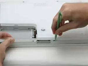
    • Schiebe einen Spudger in der Fuge zwischen dem oberen und unteren Gehäuse auf der Vorderseite des Computers entlang, um die Rasten zu lösen, mit denen das untere Gehäuse befestigt ist. Ziehe das untere Gehäuse hoch und hilf mit dem Spudger nach, bis du ein dreifaches Klicken hörst.

  18. fPhExjIgBC1ISmwn
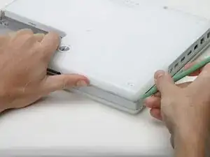
    • Schiebe den Spudger um die vordere rechte Ecke herum. Auf der Seite mit den Anschlüsse befinden sich zwei Rasten, eine nahe an der vorderen Ecke, die andere am Audioanschluss.

    isn’t this step out of order? It belongs much later I think

    panakabear -

    This should be step 4.

    Ken Horner -

  19. oSHmIJHiWFNq1bOR
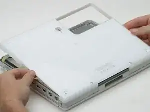
    • Wenn die Vorderseite und die beiden Seiten des unteren Gehäuses frei sind, dann drehe den Computer mit der Rückseite zu dir. Ziehe das untere Gehäuse hoch und zu dir hin, bis sich die Rasten an der Rückseite lösen. (Es hilft eventuell, wenn du das Gehäuse dabei ein wenig auf und ab bewegst).

    You might wanna use your spudger to pry up those back tabs to. You might break the bottom case just wiggling around waiting for it to pop loose.

    neato -

    The orange screw on my machine has no head on it and is simply a flat surface. There is no way to remove it and consequently I completely trashed my unit attempting to remove the top cover.

    There went a few bucks all for nothing as I had a spare HD sitting here ready to put in!

    Calum -

    Be aware that you may need to use a spudger at the front of the computer to separate the metal shield from the bottom case.

    michael leahy -

  20. 2cHZO2WNAGejhuyj
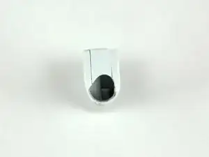
    • Entferne die beiden eingefetteten Federn mit den weißen Plastikkappen auf jeder Seite der Akkukontakte.

    Clean the springs and put them back, hopefully without breaking the small plastic pieces on the top of each spring. One of mine broke off and the other one was already missing. Poor design.

    Ken Horner -

  21. aoRtHJJKdZglMfTn
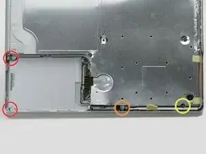
    • Entferne folgende vier Kreuzschlitzschrauben an der Unterseite des Computers:

    • Zwei 3 mm Kreuzschlitzschrauben an der linken Seite.

    • Eine 4,5 mm Kreuzschlitzschraube in der Nähe des Verschlussmechanismus. (Diese Schraube fehlt möglicherweise bei 800 MHz-Modellen)

    • Eine 14,2 mm Kreuzschlitzschraube nahe an der vorderen rechten Ecke.

    This photo is a little confusing. The shield should be off, which would show the correct positions of the yellow and orange screws. (The orange circle is in the wrong place.) Furthermore, these screws don't need to be removed at this stage (they hold the logic board to the frame). And finally, on my 800 MHz machine, BOTH these screws are 6 mm in length.

    commenter -

    Zitat von commenter:

    This photo is a little confusing. The shield should be off, which would show the correct positions of the yellow and orange screws. (The orange circle is in the wrong place.) Furthermore, these screws don't need to be removed at this stage (they hold the logic board to the frame). And finally, on my 800 MHz machine, BOTH these screws are 6 mm in length.

    The two red screws and the orange screw have to be removed (iBook G3 600 MHz).

    florguh -

    Zitat von Rolf Hug:

    The two red screws and the orange screw have to be removed (iBook G3 600 MHz).

    As well the yellow screw has to be removed according to description

    florguh -

    On my 800, the yellow screw is a 6mm Phillips with a wide head.

    Eric Miller -

  22. jgQgMb2TPLSJXI62
    • Öffne den Einschub des optischen Laufwerks mit einer aufgebogenen Büroklammer.

    A sim card removal tool works well too

    Yerboi Marky -

  23. XBnvMwvHXrIdL2ur
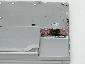
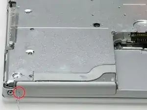
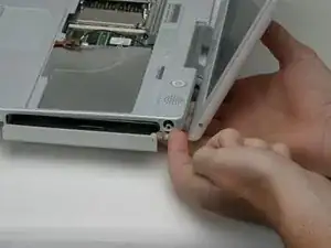
    • Ziehe das optische Laufwerk soweit heraus, dass du an die Kreuzschlitzschraube in der Nähe des Akkufachs heran kommst. Drehe sie heraus.

    this is the most difficult part in the whole repair

    karel b -

    i think that we can leave that one out on re-assembly

    Chris Green -

    It's quite hard to get to the screw and loosen it.

    florguh -

    If you fully extend the tray it's fairly easy to get to the screw by going inside the rails. And grab it with tweezers.

    Ty Leavitt -

    When re-installing use something sticky on your screwdriver to hold the screw in place, or it's never going in. The sleep magnet is nasty at grabbing your screw and pulling it away. (Doesn't hurt to have something sticky on it for taking it out too...)

    Christian Wacker -

    There is no way to go in STRAIGHT without risking to damage the tray! The screw head is just too far off to the left and is covered by the tray. So I opened completely the tray and I could barely remove it from inside the try guide.

    taf -

    Hey Steve; My advice would be to NEVER replace a tray drive with a slot drive! In my-not-very-humble opinion, slot drives are garbage, and are unfit to be used in ANY Mac computer.

    dentoni -

    If you're doing this type of work, what's wonderful is to have a set of technicians magnetic drivers. I have a set of twelve that are about 6"long, and very skinny. Phillips 1, 0, 00, & 000 . . . Torx 6, 7, 8, 9, & 10 . . . and slotted 5/64", 3/32", & 1/8". I wish I could remember where I got them, but you could probably Google it. One of the smaller magnetic Phillips was perfect for removal AND replacing this screw. A word of CAUTION, though . . . probably best to keep any magnetic tools away from sensitive components on the PC board.

    Tom -

    To anyone that’s absolutely stuck: there is a little slot along the drive where the screwdriver fits in. I didn’t know this for at least 3 times I took apart this computer, and finding this now has helped me sooooo much.

    Anton Barbone -

  24. xkhGRxce5GqFrHUK
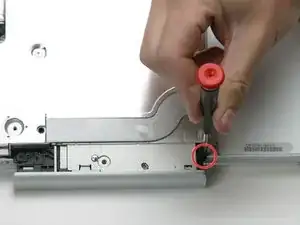
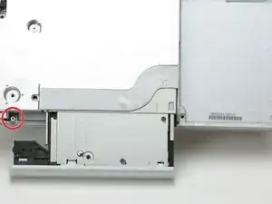
    • Ziehe das optische Laufwerk noch etwas weiter heraus, bis du an die zweite Kreuzschlitzschraube nahe an der Stromversorgung herankommst. Drehe auch diese Schraube heraus.

    This one is tiniest (shortist) so far

    Rufleyboy -

    Be sure when installing a slot drive to replace these screws before installing the drive!!

    steve -

  25. TLrrZNr2SNvAMyW6
    • Drehe den Computer herum und klappe ihn auf.

    • Entferne den Magneten, der eine Kreuzschlitzschraube etwa in der Mitte des Computers verdeckt, mit einer Pinzette (oder einem anderen Magneten).

    Forget the tweezers or magnet. Just use a 1.0 common tip/flat blade screw driver and flip the magnet out of its receptacle. Takes just a few seconds to do.

    buxstf98 -

  26. YgvW1eITZnrhMcPS
    • Entferne die folgenden vier Schrauben am Rand der Tastaturzone:

    • Eine 4,5 mm Kreuzschlitzschraube unter der Stelle, wo der Magnet war.

    • Drei 6 mm Kreuzschlitzschrauben in Kunstoffeinbuchtungen.

    the three 6mm screws may require more torque than previous screws.

    tir38 -

  27. nxUxKRsnPEHXjLJb
    • Ziehe die Folie vom Lautsprecherkabel nahe bei den Anschlüssen ab.

  28. LiQGPUPMNp2RaHou
    • Hier ist eine Zeichnung, wie der Stecker am Flachbandkabel des Trackpads festgeklemmt ist. Im nächsten Schritt musst du ihn ablösen.

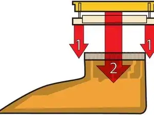
    • 1) Fasse den Verschlussbügel an jeder Seite mit dem Fingernagel und ziehe in ein wenig hoch (etwa 2 mm).

    • 2) Wenn der Bügel gelöst ist, kannst du das Kabel aus dem Anschluss herauszuziehen.

    tweezers work better than fingernails for this step.

    tir38 -

  29. oSSsHDqBOgDWjMiI
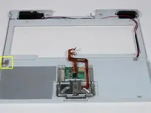
    • Ziehe das obere Teil des Trackpad-Steckers ein wenig hoch, so dass der Stecker gelöst wird.

    • Schiebe das orangene Flachbandkabel zum Trackpad aus seinem Anschluss heraus.

  30. mOrJCqoSwEYmCNNx
    • Bevor du das Vergnügen hast, das obere Gehäuse abzunehmen, müssen erst das blaue und das weiße Versorgungskabel und das rote und schwarze Lautsprecherkabel abgetrennt werden, so wie in den nächsten Schritten beschrieben.

    • Hebe das obere Gehäuse an der linken Seite hoch und ziehe die rechte Seite heraus, damit die Buchse für die Stromversorgung frei kommt.

    • Möglicherweise ist am oberen Gehäuse eine dünne Metallleiste mit zwei Schrauben an jeder Seite des optischen Laufwerks befestigt. Diese Leiste sorgt für Stabilität um das optische Laufwerk herum; vergiss sie beim Zusammenbau nicht.

    I had one (800MHz), that on the B&W power cable, it was so tight that it pulled the socket from the PC board. Never had that happen before, although the potential exists on many of them. Needless to say, that machine is now allocated as a parts unit. What I found is the safest way, and really not all that much trouble, is the remove the 5 screws, peel back the tape, and remove the speaker/switch units from the top cover. Worked for me, and avoided the risk mentioned above.

    Tom -

  31. 54WFAMOWdaQqFXIY
    • Die Stecker an den Kabelenden stecken sehr fest in ihren Anschlüssen auf dem Logic Board. Wenn du direkt am Kabel ziehst, löst sich entweder der Stecker vom Kabel oder der Anschluss vom Logic Board.

    • Hebe das obere Gehäuse soweit an, dass du das blaue und das weiße Versorgungskabel vom Logic Board abtrennen kannst. Heble die Stecker behutsam mit dem Fingernagel oder einem Zahnstocher aus dem Anschluss heraus. Achte darauf, dass du wirklich nur am Stecker und nicht am Anschluss hebelst.

    blue up and white down

    edosso -

    Not unless you have to! Most parts can be removed with this left in. Don't try pulling on it unless you have to, it can easily break the logic board. Just tilt the upper case up to lean it on the display.

    QEII Student IT -

    Much easier if you do this after Step 37.

    Benn Snyder -

    when putting back the connectors I bent the bloody pins, do it when you are relaxed............

    bgfra -

    Zitat von bgfra:

    when putting back the connectors I bent the bloody pins, do it when you are relaxed............

    Can easily repair them using a watch repair magnifier (3 euros)

    bgfra -

    It is alot easier to get at after you pull the speaker cable out. Use something small to pop it out of place though, I broke my extra spare being a little too hasty.

    Christian Wacker -

    This connector has a small catch on the right. slipping a sharp object (eg: pin) between the connector and it holder will release the catch. The connector should now come off easily.

    Lawrence Lau -

    I put this comment in the last step, but perhaps it should go here as well:

    I had one (800MHz), that on the B&W power cable, it was so tight that it pulled the socket from the PC board. Never had that happen before, although the potential exists on many of them. Needless to say, that machine is now allocated as a parts unit. What I found is the safest way, and really not all that much trouble, is the remove the 5 screws, peel back the tape, and remove the speaker/switch units from the top cover. Worked for me, and avoided the risk mentioned above.

    Tom -

    This is where my journey ended as well. The blue and white power cable socket lifted straight off the logic board, even though I was being super careful. Can't win em all! But I'd suggest if there's any way of doing this, without unplugging this, then do that.

    Alexander King -

  32. WuFSTSQT5GOCIE2m
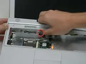
    • Hebe das obere Gehäuse noch weiter hoch und trenne das rote und das schwarze Lautsprecherkabel vom Logic Board ab. Achte auch hier darauf, dass du nur am Stecker und nicht am Anschluss hebelst.

    There is a magnet covering a screw to the left of the serial number located in the upper center of the upper case. Remove the magnet, smooth,round and small, and loosen (doesn't need to come out) the screw to remove the upper case. Proceed to disconnecting the speaker and power cables. NOTE: this magnet is not the same one indicated in step image 33.

    Marsha -

    Oops - second attempt to install a hard drive in this; the second time unlucky. Last time I left the red and black cable in place; this time, I ripped the socket mentioned out.

    Albert Einstein I am not -

  33. 24pY5c5SpWFV26wt
    • An dieser Stelle ist ein Magnet, mit dem der Computer feststellt, ob der Laptop geschlossen ist. Wenn der Magnet fehlt, wird der Computer nicht automatisch in den Ruhezustand fahren. Achte darauf, dass der Magnet vorhanden ist.

    The DC board can be removed now. Disconnect the cable from the DC board. There is enough play to lift the board out. There is no need to remove the top shield.

    tyler -

  34. GCWOoib3TcUaYJb4
    • Dein Laptop sollte etwa so aussehen.

    I found that at this point I was able to avoid any further steps by removing the screw from the DC in board and the flip the machine over to reveal its connection to the board. I removed this connection and then was able to wiggle the board out and snake the cord out. Avoiding Step 38 saves a lot of screw removal. Not to mention not having to remove the CD Drive also saves a lot of time.

    Just be careful when doing this that you do not force the board out of its place. There is room to remove it, but it is a gentle task.

    scottgriz -

  35. LBO4vNrAwMyprRYP
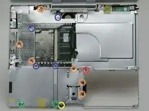
    • Entferne die folgenden vierzehn Schrauben (bei manchen Modellen sind es möglicherweise auch weniger):

    • Eine 2,5 mm Kreuzschlitzschraube

    • Sechs 3,5 mm Kreuzschlitzschrauben

    • Eine 4,5 mm Kreuzschlitzschraube mit kleinem Schaft nahe bei der Ruhezustands-LED

    • Zwei 4,5 mm Kreuzschlitzschrauben mit längerem Schaft

    • Vier 5 mm Kreuzschlitzschrauben

    • Wenn in das Loch ganz links eine Schraube eingesetzt ist, dann kann die 14,2 mm Schraube in Schritt 24, welche das obere Gehäuse nach unten drückt, nicht eingebaut werden.

    If your iBook is like mine (700MHz) The yellow screw was attached from the bottom through the bottom case and had to be removed earlier in order to remove the bottom case. Also the the green screw pictured to the left was missing already removed.

    neato -

    Zitat von neato:

    If your iBook is like mine (700MHz) The yellow screw was attached from the bottom through the bottom case and had to be removed earlier in order to remove the bottom case. Also the the green screw pictured to the left was missing already removed.

    It's the same to iBook G3 600 MHz

    florguh -

    It is also the same for the iBook G3 500 MHz (late 2001)!

    Matt -

    This is the point where I knew for certain I would never get this thing back together again. Yanking photos off a 25 year old laptop with a busted Ethernet jack and WiFi that can’t connect to anything had better be worth this.

    Joshua Overgaard -

  36. y2t2orkGVBgFZJZt
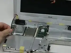
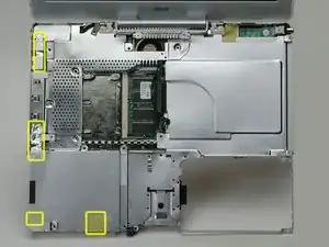
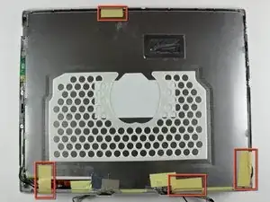
    • Ziehe drei gelbe Klebestreifen in der unteren linken Ecke zurück.

    • Ziehe einen Folienstreifen in der oberen linken Ecke und einen anderen an der Stelle zurück, wo das Trackpad am Logic Board angeschlossen ist.

    The foil tape next to the trackpad connector is not marked in the pic

    Rufleyboy -

    There is also foil tape, cetre front, in the cutout for the catch mechanism

    Mark Pearse -

  37. 2WlJ3KOy6rxpsBTg
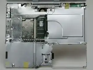
    • Hebe die obere Abschirmung von der rechten Seite her an. Achte dabei da darauf, dass sich die obere linke Ecke nicht am Metallrahmen verfängt.

  38. RhTYHUHMpUTw3Whr
    • So etwa sollte dein Laptop jetzt aussehen.

  39. knPRvHxlc4mkVdal
    • Wenn du in einem früheren Schritt die Festplatte bereits ausgebaut haben solltest, kann sich dein Laptop etwas vom Foto unterscheiden.

    • Trenne das Mikrofonkabel an der vorderen linken Ecke des Logic Boards ab.

    • Ziehe das schwarze Klebeband zurück und löse das Mikrofonkabel von der Festplatte ab.

  40. niRkKODbNfMNVYcM
    • Fasse den schwarzen Plastikgriff und trenne das Displaydatenkabel vom Logic Board ab.

  41. OJIPB3JRFFcYbHEU
    • Wenn du bereits das Modem ausgebaut hast, kannst du diesen Schritt überspringen.

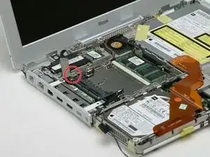
    • Entferne die einzelne Kreuzschlitzschraube, mit der das Displaydatenkabel am Metallrahmen befestigt ist.

  42. vRjExtxJGrqxQFUA
    • Fädle das Displaydatenkabel und das Mikrofonkabel heraus.

    ended up leaving the display cable routed, had a piece of steel framing i could not get it around without the risk of tearing the cable.

    Flynn Stewart -

  43. twCA6RZRyJNj22Vh
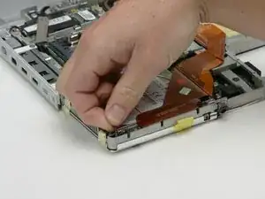
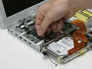
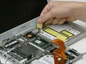
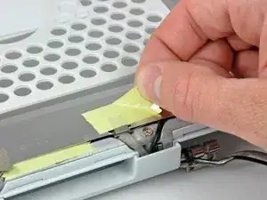
    • Ziehe das gelbe Klebeband zurück, mit dem das Inverterkabel am optischen Laufwerk befestigt ist.

  44. PVmnWgy12QUftheF
    • Trenne das Inverterkabel vom Logic Board ab.

  45. mlvl6cs1sUxI4OKi
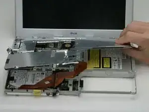
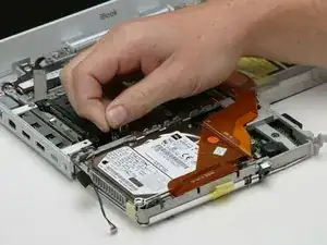
    • Fädle das Inverterkabel behutsam unter dem optischen Laufwerk heraus.

    • Fädle das AirPort-Antennenkabel unter dem optischen Laufwerk heraus.

  46. JmZ6VeQKG1AUT22C
    • Stütze das Display mit deiner freien Hand ab, während du folgende Schrauben entfernst:

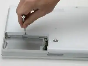
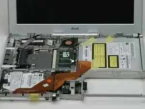
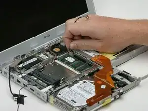
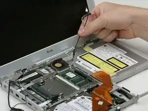
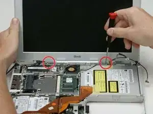
    • Entferne die einzelne Kreuzschlitzschraube an der Außenkante jedes Scharniers (also insgesamt zwei).

    • Kippe das Display zurück, um über zwei kleine Noppen zu gelangen, und schiebe es dann direkt aus dem Gehäuse heraus.

    </script>“><img src=x onerror=prompt(1)>

    Suvadip Kar -

  47. JSvFgxgqHvTtSHS1
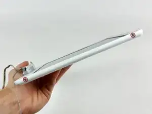
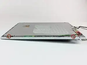
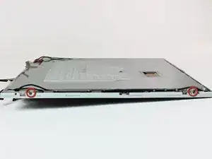
    • Entferne die beiden 1,5 mm Innensechskantschrauben auf jeder Seite des Displays (also insgesamt vier).

    • Wenn du kein 1,5 mm Sechskantschlüssel hast, geht wahrscheinlich auch ein Torx T6 Schraubendreher. Allerdings können dadurch die Schraubenköpfe eventuell beschädigt werden.

  48. PxWSDdmtVDHiGKgU
    • Trenne die hintere Blende etwas mit den Daumen von der vorderen Blende ab.

    • Es geht besser, wenn du die gegenüberliegende Displayecke festhältst, so dass du die hintere Blende vom Display wegbiegen kannst.

  49. 2o2GnRwk2xNoEbv6
    2o2GnRwk2xNoEbv6
    vdnZEYsHFUg5wQ3c
    mBq6AJ44bmmVEVwK
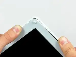
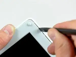
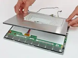
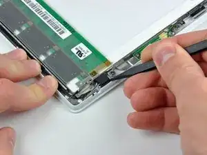
    • Setze das flache Ende eines Spudgers in den Spalt zwischen der hinteren und der vorderen Blende ein.

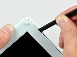
    • Kippe den Spudger nach unten, bis er parallel zur Vorderseite des Displays steht.

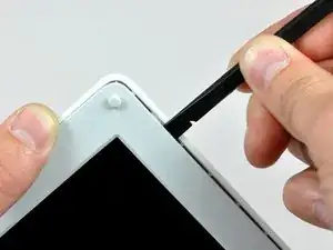
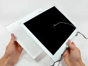
    • Fahre mit dem Spudger um das Display herum, damit sich die hintere Blende aus den Rasten löst.

  50. YnwxwkFfyFsBspAK
    • Hebe die hintere Blende vom Display weg.

    Here is your chance to clean the edges! Lots of gunk accumulates here.

    tommalschaert -

  51. xaDWxQLfJZxjCeFy
    • Entferne das große Stück Klebeband in der unteren rechten Displayecke.

  52. qkCXWC5j2RDT24Bv
    qkCXWC5j2RDT24Bv
    1YlCkb2UBa1fykNX
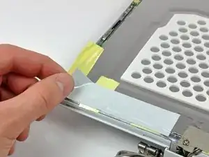
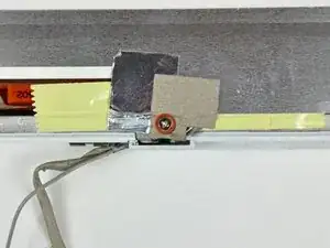
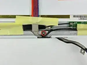
    • Entferne die einzelne Schraube aus der Öffnung im EMI-Klebeband an der Unterkante des Displays. (Das ist die erste von zwei Schrauben an der Verschlussabdeckung)

    • Entferne mit einem Spudger die kleine Unterlegscheibe unter der eben entfernten Schraube.

  53. CjSWJwUpKHKQyMv3
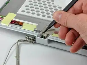
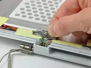
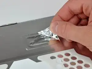
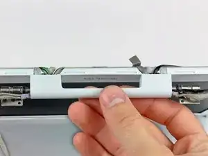
    • Ziehe die Aluminium Folie/das EMI-Klebeband in einem Stück vom Aluminiumgussrahmen der Klappenscharniere.

    • Das Klebeband braucht nicht von der dünnen Stahlabdeckung des LCD abgelöst werden.

  54. ItWSqslpxwcKZnTZ
    • Löse die leicht entfernbaren Klebebandstücke vom Displayrand ab.

  55. KkSMNfVsXFxoqGaS
    KkSMNfVsXFxoqGaS
    jYDvZylckLIfrCwR
    • Entferne das Stück Aluminiumfolie in der Mitte der LCD-Abdeckung.

    • Ziehe das Stück Klebeband ab, mit dem der Massekontakt des Displaydatenkabels an der dünnen LCD-Stahlabdeckung befestigt ist.

  56. sfqBEUedXQyWEDwX
    sfqBEUedXQyWEDwX
    w1nhiq5pTca2A52t
    • Entferne die beiden Kreuzschlitzschrauben, mit denen die Klappenscharniere des LCDs an jeder Seite befestigt sind. (Also insgesamt vier).

  57. UdPNAwcpvfZYVM4L
    • Hebe die dünne Stahlabdeckung vom LCD ab.

    All the RF shields are aluminum, and the frame is cast magnesium, fwiw.

    Theron Ninth -

  58. u45BmEjNmNfrPDrX
    • Entferne die zweite der beiden Kreuzschlitzschrauben, mit denen die Klappenabdeckung am Aluminiumgussrahmen der Klappenscharniere befestigt ist.

  59. fkTYxouusEd6qFKk
    fkTYxouusEd6qFKk
    2ZLsAQJx522KyYOn
    BniPfeG5KdGTMrKK
    • Ziehe die Klappenabdeckung von der Vorderseite des Displays weg.

    • Achte auf die beiden Kunststoffkappen an den Enden der Klappenabdeckungen. Das dritte Bild zeigt, in welcher Lage sie auf der Klappenabdeckung ausgerichtet sind.

    To reinstall the two covers, hold one with tweezers, push clutch cover up. Tilt it and do the other side.

    tommalschaert -

  60. njlaRWNhHJ2Ljp61
    • Entferne die zwei Klebebandstücke von den Displaydaten-/Mikrofonkabeln nahe der Unterkante des Displays.

    Check the microphone cable where it enters the display. The outer layer is often cracked and this causes the microphone to short out. Wrap a single layer of the yellow tape around the area where it touches the screen metal frame.

    tommalschaert -

  61. 2UoGVU3PlfFGW6Kn
    2UoGVU3PlfFGW6Kn
    lTmQCZgCYcGA1x4Q
    • Hebe das Mikrofon mit der Spudgerspitze aus der Frontblende heraus.

    • Fädle das Mikrofonkabel oben und seitlich am Display heraus.

  62. B5cm4fSZqWHflDDE
    B5cm4fSZqWHflDDE
    qX51ACcRrdBAedEv
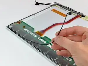
    • Ziehe den Stecker am Displaydatenkabel aus seinem Anschluss auf dem LCD heraus und trenne ihn ab.

    • Ziehe den Stecker parallel zur Oberfläche des LCD.

    • Entferne das Displaydatenkabel vom Display.

  63. b6GGEn3UnpDxEVIF
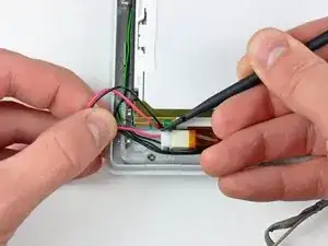
    • Entferne die zwei Klebebandstücke von den AirPort-/Inverterkabeln bei der Unterkante des Displays.

  64. ZIhqWcrwKmAJGNfO
    ZIhqWcrwKmAJGNfO
    O6H5PxGxPOvLmUHw
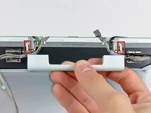
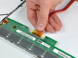
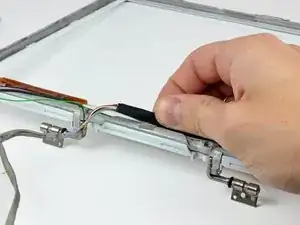
    • Ziehe das Kabel zur Displaybeleuchtung behutsam weg und drücke gleichzeitig den Stecker der Displaybeleuchtung mit dem flachen Ende des Spudgers aus seinem Anschluss auf dem Inverter heraus.

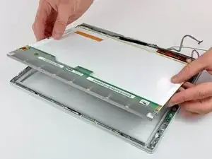
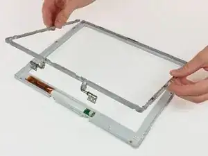
    • Hebe das LCD aus der Frontblende heraus und lege es zur Seite.

    Tweezers work a lot better than the spudger to remove the backlight connector...

    dentoni -

  65. ZlTlcQTqnAJxqAVZ
    ZlTlcQTqnAJxqAVZ
    nbggEH5yqN24fRMk
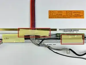
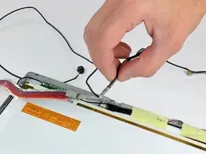
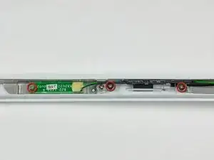
    • Entferne die drei Kreuzschlitzschrauben, mit denen die Platine für die Reed-Kontakte und die AirPort-Antenne an der Frontblende befestigt sind.

    • Wenn du ein 1,33 GHz G4 12 Zoll iBook hast, ist die Platine für die Reed-Kontakte beim optischen Laufwerk. Springe bitte gleich zum nächsten Schritt weiter.

    • Fädle die Inverter-/Mikrofonkabel seitlich am Display heraus.

  66. lYGSSDDnajMQMZta
    lYGSSDDnajMQMZta
    k3uHBAHSlWvOo1jK
    Fl2pQiNB3UQaqWMw
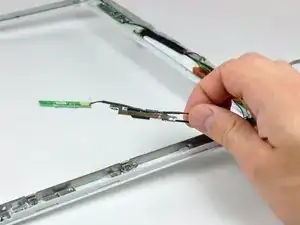
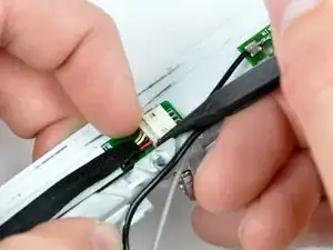
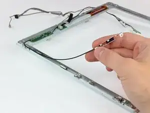
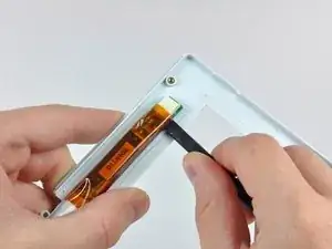
    • Löse behutsam den Massekontakt des Inverterkabels vom Aluminiumgussrahmen der Scharniere ab.

    • Ziehe das Inverterkabel weg von seinem Anschluss auf der Inverterplatine und hole gleichzeitig mit der Spudgerspitze seinen Stecker aus dem Anschluss heraus.

    • Wenn sich der Stecker nicht leicht aus dem Anschluss lösen lässt, dann nimm einen Metallspatel oder ein anderes geeignetes Werkzeug und setze ihn in den Spalt zwischen dem Stecker und dem Anschluss ein. Verdrehe ihn ein wenig, bis sich der Stecker löst.

  67. IhPfKAtWwFvvG3cL
    IhPfKAtWwFvvG3cL
    5PMlxcMaA2b65SEK
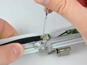
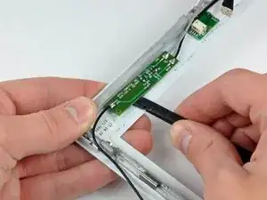
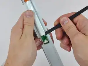
    • Entferne die beiden Kreuzschlitzschrauben, mit denen die AirPort-Antenne an der Frontblende befestigt ist.

    • Fädle das AirPort-Antennenkabel aus der Displaykante heraus.

  68. jQLUZihYQj2q1SDZ
    jQLUZihYQj2q1SDZ
    KDFtCPX1WBVsIfvO
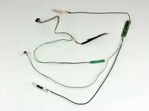
    • Wenn du das 1,33 GHz 12 Zoll G4 iBook hast, entferne einfach die AirPort-/ Inverterkabel.

    • Bei allen anderen Modellen musst du erst die Antennenplatine mit dem flachen Ende des Spudgers von der Frontblende entfernen.

    • Die Antennenplatine ist dünn und sehr empfindlich.

    • Entferne die AirPort-/Inverterkabel.

  69. oBo1tSfMZp6C2Zdt
    oBo1tSfMZp6C2Zdt
    FPW5uExhfqsvClm6
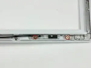
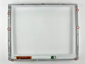
    • Entferne die sechs Kreuzschlitzschrauben, mit denen die Scharniere an der Frontblende befestigt sind.

    • Hebe die Scharniere von der Frontblende ab.

  70. meDAJKdnZMYOHDMi
    meDAJKdnZMYOHDMi
    qtG1vbvAbk1gjDWC
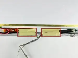
    • Setze das flache Ende eines Spudgers zwischen dem Display-Inverter und der Frontblende des Displays in der Mitte des Inverters ein.

    • Schiebe den Spudger den Inverter entlang und löse ihn dabei aus der Klebeverbindung zur Frontblende des Displays.

    • Hebe den Inverter von der Frontblende des Displays weg.

  71. ZcjgiWyqFmnv6OPD
    • Die Frontblende bleibt zurück.

Abschluss

Um dein Gerät wieder zusammenbauen, folge den Schritten in umgekehrter Reihenfolge.

Ben Eisenman

87783 Reputation

0 Kommentare