Einleitung

Das 56k interne Modem ist Standard bei allen Modellen.

  1. twUoDXEVMw6TP6JK
    • Nimm eine Münze und drehe die Verriegelungsschraube des Akkus um 90° im Uhrzeigersinn.

  2. JbLkX3rgRZXxaRHj
    • Hebe den Akku aus dem Computer.

  3. 1eNPtylhoCMCYMKe
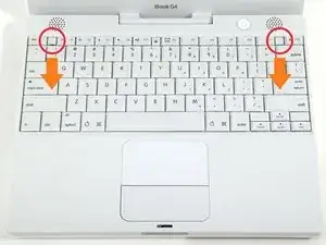
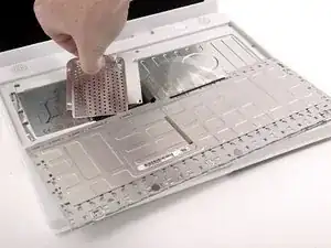
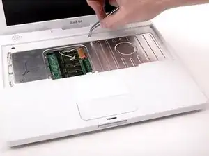
    • Ziehe die beiden Sicherungslaschen der Tastatur zu dir und hebe hoch, bis die Tastatur herauskommt.

    • Wenn sie nicht freikommt, drehe die Sicherungsschraube der Tastatur um 180°, egal in welcher Richtung und versuche es nochmals.

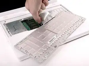
    • Klappe die Tastatur vom Display weg um und lege sie mit den Tasten nach unten auf das Trackpad.

    The "keyboard locking screw" is a transparent plastic screw located between F5 and F6 function keys.

    Nienpo -

  4. owTVvfcCh3TnSjwL
    • Wenn eine AirPort-Karte eingebaut ist, dann folge den nächsten drei Schritten, um sie zu entfernen.

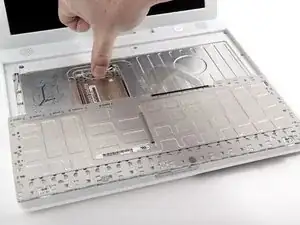
    • Drücke die Klammer für die Kabel von der AirPort-Karte weg zum Display hin, drehe sie dann und löse sie von der RAM-Abschirmung.

    To put back the AirPort card with the clasp (wire brace), make sure the card is pushed against by the wire, not clamped over. The latter situation indicates that the card is not seated deeply enough.

    Nienpo -

  5. yicPdyYRcJc2fZQW
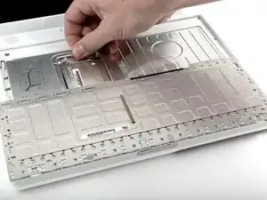
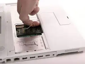
    • Fasse die durchsichtige Kunststofflasche an der AirPort-Karte und ziehe sie zum Display hin.

  6. hnDgOCwD21LyDf5a
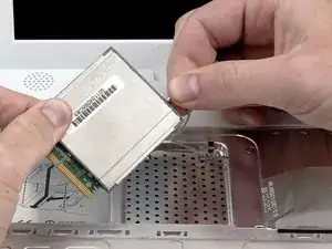
    • Halte die AirPort-Karte in einer Hand und entferne mit der anderen Hand das Antennenkabel.

    I had a hard time getting the Airport card seated properly when reconstructing. If the wire brace doesn't snap back in easily, then try reseating the card. Don't force it.

    vorski -

    THANK YOU SO MUCH FOR THIS TUTORIAL!

    Honestly, this is a lot easier than it looks. The key is take your time and don't force anything. Use tweezers to disconnect cables from logic board. Also, use a mini-head screwdriver like for glasses to pry the case open and go slowly.

    headphonz -

    Very well explained. Thank you. I had some donated memory cards and had to try twice before success. I found that I did not have to remove the antenna from the airport express and I did not have to remove the keyboard plug from the processor. Enough room to remove and replace memory card with it in.

    Jay Speaks -

  7. 6T3ZI4UT2cnh2A1Z
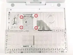
    • Entferne die vier silbernen Kreuzschlitzschrauben, mit denen die RAM-Abschirmung befestigt ist.

    very gently magnetizing my small philips screwdriver was a HUGE help when putting all the tiny screws back into place... all said and done, there will be a lot of teeny screws to be taken out and put back. To magnetize the screwdriver, I just rubbed it several times in one direction (similar to sharpening a knife) across a strong refrigerator magnet... you only want it just strong enough to hold a screw, but not so magnetized that it corrupts your new hard drive!

    Sean Franzen -

  8. gPM5r6JJrEhsQqVW
    • Fasse die Metallhalterung oben an der RAM-Abschirmung, ziehe nach oben und entferne die Abschirmung.

    When replacing the RAM shield, make sure to pull the antenna cable through the tiny slot in the upper right, or else you'll have to unscrew it all over again.

    demifugue -

  9. uSc61GSOJCETMTIT
    • Ziehe das Tastaturkabel vom Logic Board nach oben, halte es dabei so nahe wie möglich am Stecker.

    • Achte darauf, dass das Tastaturkabel eingesteckt ist, bevor du die RAM-Abschirmung befestigst.

  10. YRb1icXGroZFsR5Q
    • Nimm ein geeignetes Werkzeug und entferne die drei Gummifüße vom Gehäuseunterteil.

    Be careful that the feet don't shoot up and hit you in the eye when you pry them out!

    UniAce -

    Each rubber foot has three large tabs occupying 3, 7, and 11 o'clock positions, while a small tab at 9 o'clock position. When you place those rubber feet back to the ring housings, make sure their small tabs aligning with the opening gaps around the rings.

    Nienpo -

    Taking the feet off - I found a thin flathead screwdriver was much better than a pin to lever them off. Also doesn't mark the rubber. Not hard though

    tangawk -

    I agree with tangawk: with a flathead screwdriver it was a lot easier. One have just to go deeper enough under the tab to be effective. Just be careful: the tab could jump far.

    chmilblick -

  11. j4Nx3eLjBY5GiZKS
    • Entferne die jetzt sichtbaren drei Kreuzschlitzschrauben.

  12. GUGUQtPMWADopEA4
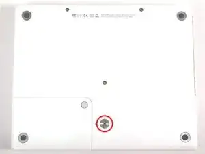
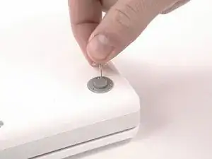
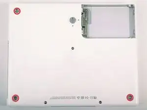
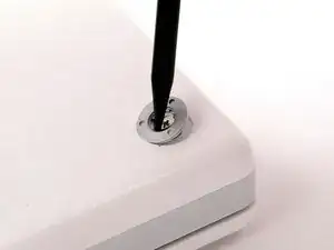
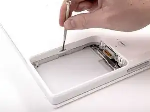
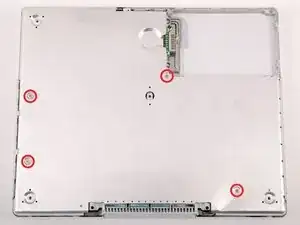
    • Heble die drei Metallringe, mit denen die Gummifüße befestigt waren, mit einem Spudger oder einem kleinen Flachschraubendreher nach oben.

    Align the ring so that it sits flush before trying to put the screws back in. A small tab in the case needs to align with the ring correctly.

    jaeckerb -

    Yes, the rings have to be put back and flushed with the lower case surface. Otherwise, the rubber feet will not stand evenly.

    Nienpo -

  13. LZ1IWs35gP1IjjJA
    • Entferne die drei Torx T8 Schrauben.

    • Die kürzere Schraube ist in der Mitte des Computers.

    I was able to use a hex wrench since I didn't have a #8 Torx screwdriver.

    jackshim -

    Zitat von jackshim:

    I was able to use a hex wrench since I didn't have a #8 Torx screwdriver.

    I, however, was not.

    rbrtrx -

    These 3 screws actually use 2mm Allen (hex) heads, so try to find one of those first (they come in many metric Allen sets) before resorting to the T8 Torx.

    Bryan -

    If you save your IKEA wrenches from their steel cable "curtain rods," you will have a 2mm hex wrench or two to spare; the 2mm wrenches are used to tighten the pair of set-screws holding each end of the cable into the wall-mounting.

    The three sets of metric allen wrenches I'd accumulated over the years did NOT contain that itty-bitty 2mm wrench, and I didn't want to try forcing a torx-fit.

    However, when I finally thought to check, I DID have a 2mm hex "screwdriver tip" in a large "universal set" of odd magnetic screwdriver tips--one with things like hollow-pointed torx, hollow-pointed hex, pin tips (imagine a flat-bladed tip with the middle 1/3 removed)--those so-called "tamper-resistant" screw heads (no triangle points, though, for all the kids' toys made in China).

    And why hadn't I thought to look in the screw driver set first thing? Because the hex 2mm was a WRENCH, not a screw with a hexagonal driver tip. Talk about limits imposed by "context" or "framing"--and age.

    Theron Ninth -

  14. vV1hcCItPc4PT4fc
    • Entferne die beiden Kreuzschlitzschrauben an den beiden Seiten der Akkukontakte.

    If I am not mistaken, these two screws have slightly heavier heads than all the others, in case this is helpful info for when you reassemble.

    akatodd -

  15. bMYtvwBgcOmsXLKo
    • Atme tief durch, es kommen einige schwierige Dinge auf dich zu, wir versprechen aber, dass das Gehäuseunterteil abgelöst sein wird.

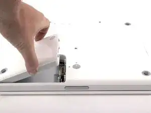
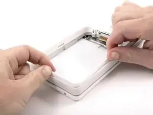
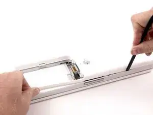
    • Drücke die dünnen Ränder des Gehäuseunterteils, die das Akkufach umgeben, nach innen, biege sie über die Laschen hinaus und hebe sie dann an, um diese Ecke des Gehäuseunterteils zu lösen.

    I need patience and I need it NOW!!!!

    chrisbulle -

    They aren't joking about these being trying times. Steps 15-20 are tough, especially if you don't have a spudger. A small flathead screwdriver works, but will scratch/nick your case.

    vorski -

    I killed my spudger on this step, trying to twist it in the seam to lift the cover up. I got better progress using it to pry out the gey band, surrounding the laptop. That action will release the catch grooves. Still a test of patience...good luck.

    karenskirka -

  16. DOOq4avnnBVURRIm
    • Am Steg im Akkufach ist ein Schlitz, mit dem das Gehäuseunterteil festgehalten wird. Heble die untere Rille am Schlitz mit einem kleinen Flachschraubendreher heraus und ziehe das Gehäuseunterteil hoch, um den Schlitz von den Laschen zu lösen.

  17. NN2ZltRSv6HkkPAm
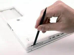
    • Führe einen Spudger entlang der Naht zwischen dem Gehäuseunterteil und dem Gehäuseoberteil, um die Laschen am Gehäuseunterteil zu lösen. Ziehe das Gehäuseunterteil nach oben und benutze wenn nötig weiter den Spudger, bis du es dreimal klicken hörst.

  18. BmsqSoCf36ihZP4E
    • Führe den Spudger weiter um die vordere rechte Ecke herum. Es gibt zwei Laschen an der Seite des Computers mit den Anschlüssen, eine nahe bei der vorderen Ecke und eine nahe beim Audioausgang.

    I used a flathead screwdriver and an old credit card instead of a spudger. If using the screwdriver, be advised it may damage the case.

    tildeksnyder -

    Wish I'd read the tip about the credit card! Made a few dents during this procedure as I didn't have a spudger. N.B. Plastic modeling tools are not suitable for this job!

    enginemonkey -

    "Continue to run the spudger around the front, right corner." This is nearly impossible for me. Instead, I use a small flathead screw driver to gently open up the tab at the corner.

    Nienpo -

  19. G5FoOIEmZhwrQP26
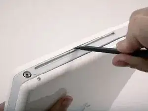
    • Bevor das Gehäuseunterteil ab geht, müssen drei Laschen über dem optischen Laufwerk gelöst werden. Schiebe einen Spudger über dem optischen Laufwerk in das Gehäuseunterteil und lasse ihn zur Rückseite des Gerätes hin laufen, bis du es dreimal deutlich klicken hörst.

    Press inwards between the case and the plastic around the drive. It'll flex the plastic around the drive in and away from the bottom case. The first is about an inch from the center of the slot, then centered on the slot and about one inch past the center.

    jaeckerb -

    Be careful here; I scratched up my case here pretty good with the flat head screwdriver I'd used.

    ejwest24 -

  20. QoHUamlI2EHRFpZ3
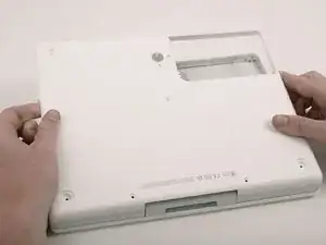
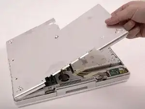
    • Wenn das Gehäuseunterteil vorne frei ist, drehe den Computer so, dass die Rückseite zu dir zeigt. Ziehe das Gehäuseunterteil nach oben von dir weg, bis die Rückseite frei kommt.

    • Es hilft, wenn du dabei das Gehäuse nach oben und unten wackelst.

    Step 20.5: Have coffee and give yourself a pat on the back...

    dennis peeters -

    Take care that the monitor cable is tucked in when putting the bottom case back on.

    jaeckerb -

  21. y6R2SPOLLv6GPWbk
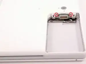
    • Entferne die kleinen gefetteten Federn mit den Kunststoffkappen an jeder Seite der Akkukontakte.

  22. 4WIuQhQXvteSJ621
    • Entferne die vier Kreuzschlitzschrauben von der unteren Abschirmung.

    • Die beiden längeren Schrauben befinden sich am Rand des Computers nahe bei den Anschlüssen.

    I leave the bottom shield. It was not necessary for me to get it of to dismount the upper top.

    Everling -

    on mine, there are six small extra screws to remove.

    dianadipilla -

  23. 35fJKmvdXelMCXq2
    • Hebe die untere Abschirmplatte ab.

  24. fQJ4eA5AQgv5ZJ5O
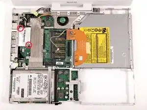
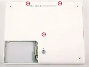
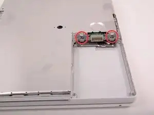
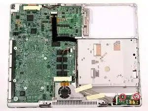
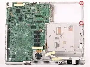
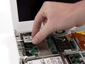
    • Entferne die beiden Kreuzschlitzschrauben, mit denen die Gleichspannungsplatine befestigt ist.

    I left the DC board alone screws, cable and all for my hard drive swap.

    jyee -

    No reason for this step or the next few when replacing the hard drive. Leave the DC board and its cable alone!

    jaeckerb -

    When re-assembling, make sure the right screw goes in the right-most hole.

    beeay -

  25. YLVJYo1s6HvJEcOo
    • Trenne das Gleichspannungskabel vom Logic Board ab.

    I found that I could leave the cable attached if I was just careful with where I placed it when I turned the computer over.

    horntaxnow -

  26. FEngxZSB43GsmG2N
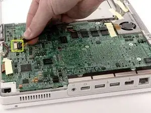
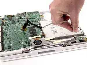
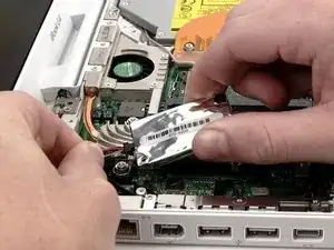
    • Löse das Kabel vom optischen Laufwerk ab, eventuell musst du Klebeband entfernen. Ziehe die Gleichspannungsplatine schräg aus ihrem Fach heraus.

  27. iAKbbSZsLPoAa5sK
    • Entferne die beiden Kreuzschlitzschrauben aus dem Akkufach.

    Very helpful!

    Gosimiera -

  28. QqkHEAZc3XjtmMDw
    • Wir empfehlen, den Computer ab jetzt auf ein großes Stück von grauer Antistatikverpackung zu stellen, damit das Logic Board nicht beschädigt wird.

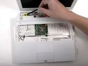
    • Drehe den Computer um und öffne ihn.

    • Heble den Magnet nach oben, er verdeckt eine Kreuzschlitzschraube nahe an der Mitte des Computers.

    Probably a good idea to follow the advice about protecting the logic board with foam. I used bubble wrap on this step, but it probably didn't provide enough padding. When I reassembled everything and booted up (successfully!) the screen had a strong bluish tint. Can't seem to get rid of it now. Oops.

    Otherwise, many thanks to ifixit and all y'alls for the helpful comments.

    Tristan Naramore -

  29. Y4MYxrMpaIPCOfXc
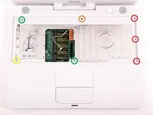
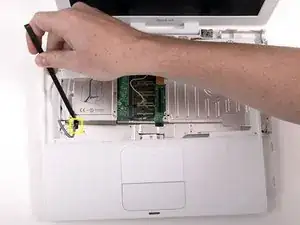
    • Entferne folgende sieben Schrauben am Rand der Zone für die Tastatur:

    • Drei 2 mm lange Schrauben am rechten Rand

    • Eine 4,5 mm lange Schraube unter der Stelle, wo der Magnet war

    • Eine 6 mm lange Schraube mit kleinem Kopf in der linken unteren Ecke.

    • Zwei 6 mm lange Schrauben mit großen Köpfen, eine in der oberen linken Ecke und eine in der Mitte

    My journey of replacing the hard drive stops at step 29. The screw marked with the yellow circle ("One 6 mm Phillips with a small head in the lower left corner") is very tight. The torque I applied wore out the screw head and it becomes the death sentence announcement of the iBook. Sad.

    Nienpo -

    I am happy to announce that my iBook gets its 2nd life with the newly implanted hard drive. The screw marked with the yellow circle was worn out. I ordered a set of "Screw Extracting Pliers" (small) from iFixit in the hope of remedying the problem. Initially, the pliers do not have enough space to work on it because the screw sits in a narrow plastic basin. I file some of the surrounding plastic away to make room. Finally, the pliers "bites" the screw out. Yes!

    The screw is put back when the iBook is assembled.

    Nienpo -

  30. DKOe4MdNjoRuAgF6
    • Bevor du das Gehäuseoberteil abnehmen kannst, musst du den Trackpad-Stecker, das blaue und weiße Versorgungskabel und das Lautsprecherkabel abtrennen. Dies wird in den folgenden Schritten beschrieben.

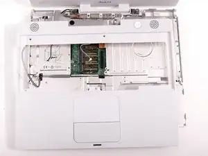
    • Hebe das Gehäuseoberteil an der rechten Seite hoch und trenne den Trackpad-Stecker ab. Er ist unter der weißen Kunststofflasche verborgen. Bei manchen Modellen kann es auch ein wenig anders aussehen.

    When replacing the upper case, after you've installed your new hard drive, make sure you remember to RECONNECT the trackpad connector. I forgot to connect it when I put the computer back together, and had to take it apart a 2nd time in order to fix my mistake. Other than that I had no problems with this upgrade thanks to the detailed instructions offered here . Thanks iFixit.com!

    You can see photos of my upgrade process here if you are interested: http://www.flickr.com/photos/judahs/sets...

    judah -

    Ty iFitit..I replaced the screen on my iBook g4...you guys rock..went without a hitch...hat sitting there for month with a hanging screen...feels good to be mobile again.... THANK YOU....

    jeremiah -

  31. YMV3VM4GubYRpYia
    • Hebe das Gehäuseoberteil sorgfältig etwas 13 mm nach oben und bewege es so, dass du an die Versorgungs- und Lautsprecherkabel herankommst.

    • Wenn das Gehäuseoberteil festhängt, müssen vielleicht die Laschen gelöst werden, mit denen das Gehäuseoberteil am Metallrahmen am äußeren Rand des Akkufachs befestigt ist.

    Neither of these pesky & fragile connectors need to be removed…leave then connected! All you need to do, is to unscrew both speakers, carefully peel their wires off the housing, and—finally—make one cut with scissors or a sharp craft-knife through the upper left aluminum shield, closest to the plug…the board will slip around the second plug without any modification…Voila! No chance of harming the plugs, and the cut is very short & may be covered with tape. I have done this on two( 2 ) of these G4’s, a 12” and a 14”, and it works like a Charm…just be careful with the speaker wires, and you’ll never have to worry about ruining a G4 again…True Story!

    Michael Maddan -

  32. rOZ4UXVlgES22vAi
    • Die Stecker an den Kabelenden sitzen sehr fest in den Anschlüssen auf dem Logic Board. Wenn du direkt am Kabel ziehst, reißt entweder der Stecker vom Kabel oder der Anschluss vom Logic Board.

    • Hebe das Gehäuseoberteil so weit hoch, dass du das blaue und weiße Versorgungskabel vom Logic Board abtrennen kannst. Heble den Stecker vorsichtig mit deinem Fingernagel oder einem Zahnstocher aus dem Anschluss heraus. Achte darauf, dass du nur am Stecker hebelst und nicht am Anschluss.

    just pulled up the socket accidentally. #&^&

    chickenbrothel -

    Zitat von chickenbrothel:

    just pulled up the socket accidentally. #&^&

    It helps to use two small tools here: A dental pick (or similar) to hold down the socket (keeps it from separating from the logic board) and a small flathead screwdriver. With your off hand, use the pick to make sure the socket stays put; with your good hand, use the screwdriver. DON'T pry; instead, TWIST the head of the screwdriver to gently coax the connector out of the socket.

    textrix -

    Tweezers were also helpful here.

    jackshim -

    I left the power button cable as it is VERY easy to break. I instead left it plugged in, and flipped the upper case and metal shield up against the screen. Worked well.

    hwn -

    I've just done the same thing DRAT ! Is there any way to solder the tiny socket back on to the board ?

    steweric -

    First I released the plastic top. Then I removed the touch pad connector. With that, I was able to shift the top case down a inch so the power connector was exposed. I pressed a small screw driver along the middle on the long side of the power connector and twisted back and forth so it would wedge the connector from the socket. I left the speaker(long wires) wires connected and just flipped the case off to the left.

    jyee -

    You don't have to remove the power button connector to remove most parts! It's really dodgy and can break your logic board. When you peel up the glue on the wire for the microphone connector, lean the upper case on the display.

    QEII Student IT -

    Wished I had read the comment BEFORE trying to pull that stupid connector out. Here is my take away: If you have an iBook 1.33 - DON'T TRY TO REMOVE THE CONNECTOR! It's impossible not to break the socket off the logic board. The connector is so firmly in the socket that you can't pull it out.

    If you broke it, there is the possibility to solder it, but it's very tricky. But maybe the only chance of saving your machine. Do some google search, there are people who've done it.

    uliverse -

    Zitat von jackshim:

    Tweezers were also helpful here.

    I used forceps. Quick and easy.

    Desert Fox -

    I also pulled the power connector from the board and had to send the board to a repair shop to have the connector soldered back on. Working on tiny surface mount components is not for the faint of heart. Sierra Circuit Repair of Chico CA did a good job but it cost me $100.

    gdavids57 -

    Zitat von QEII Student IT:

    You don't have to remove the power button connector to remove most parts! It's really dodgy and can break your logic board. When you peel up the glue on the wire for the microphone connector, lean the upper case on the display.

    Thank you very much!! Great tip, worked great,it cuts down the risk of logic board repair. I agree with the suggestion of tweezers, long thin tips help to maneuver in tight areas and are great for removing the tape holding the wires to the plastic upper case.

    Oz Leap -

    I cloned the original drive onto a larger one, and started following these instructions.

    Alas, I just "bricked" my machine as well at this step... the jack broke off the board.

    Well, it served admirably for the last few years....

    Painful but not critical lesson...

    dannyb -

    Don't forget put off the mouse pad cable

    Francisco -

    I concur, you dont have to remove the power button connector.

    Great guide...just installed a new ssd.

    Make sure you follow the OS X Installation Guide on how to partition etc...

    Banu -

  33. vK4ctYsAEvvu1oNV
    • Hebe das Gehäuseoberteil komplett ab und trenne das mehrfarbige Lautsprecherkabel vom Logic Board ab. Achte wie vorher auch darauf, dass du nur am Stecker ziehst und nicht am Anschluss.

    • Tipp: Das mehrfarbige Kabel lässt sich leichter und weniger mühsam abtrennen, wenn vorher die obere Wärmeabschirmung entfernt ist. Stütze das Gehäuseoberteil beim Entfernen der Abschirmung aufrecht ab, dann kommst du leichter an den Stecker dran.

  34. jUPecNjJcjbcsWXB
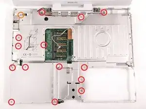
    • Entferne folgende fünfzehn Schrauben:

    • Vierzehn 3 mm lange Kreuzschlitzschrauben

    • Eine 5,5 mm lange Kreuzschlitzschraube in der oberen linken Ecke

    • Achte auf die Position des Magneten in der unteren rechten Ecke.

    This is very confusing. Next time I'm going to mark the spots where the little screws go with red sharpie.

    chrisbulle -

    On my machine, the 5.5 mm Phillips in the upper left corner had a larger-diameter head than the other screws, in case this is helpful info for when you reassemble.

    akatodd -

    screws to my left in front of pc

    eric robertson -

    It says mind the magnet position so how do I put the magnet do I just put it like the image has it??!??!?

    chizilow yt -

  35. VsFuVZjVXOBPSruX
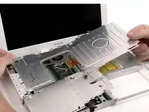
    • Hebe die obere Abschirmung an der rechten Seite nach oben. Achte dabei auf die obere linke Ecke, sie kann am Metallrahmen hängen bleiben.

  36. FPKpWSDT3WTZP1hk
    • Es gibt verschiedene Varianten des iBook G4, deswegen kann es bei dir ein wenig anders aussehen. Die Schritte sind aber für alle gültig.

    • Entferne die beiden Kreuzschlitzschrauben in den Ecken des Modems.

  37. hqIhCHdFDsTbBayi
    • Hebe das Modem und seine Abschirmung von der Unterseite ab.

  38. eCD2fOyOJ2MRZeER
    • Trenne das RJ-11 Kabel oben am Modem ab.

    • Setze beim Einbau des Modems zuerst die Abschirmung ein, schließe dann das Modem und drücke es auf der Abschirmung fest, achte darauf, dass es mit dem Logic Board verbunden ist.

Abschluss

Um dein Gerät wieder zusammenzubauen, folge den Schritten in umgekehrter Reihenfolge.

iRobot

Mitglied seit: 25/09/09

0 Reputation

0 Kommentare