Fuse(s)
These are some common tools used to work on this device. You might not need every tool for every procedure.
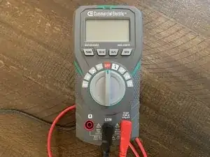
A multimeter (also called a multitester a VOM or volt-ohm-milliammeter) is an electronic measuring instrument used to measure voltage, current, and resistance of a circuit. Analog multimeters use a microammeter with a movable pointer to display readings. Digital multimeters (also called DMM or DVOM) either use a graphical bar representing the measured value or have a numerical display. Multimeters can be hand-held devices for field and basic work or bench instruments that can measure voltage, current, and resistance.
The first current-detecting device was a moving-pointer galvanometer used in 1820 to measure resistance and voltage by using a Wheatstone bridge and comparing the desired, unknown quantity to a reference resistance or voltage. Multimeters were invented in the early 1920s by Donald Macadie, who designed an instrument that could measure amperes (amps), volts, and ohms. This first multimeter was hence called the Avometer.
Multimeters generally include a display (either analog or digital), a selection nob, and ports. The selection knob allows users to set the multimeter to read milliamps (mA) of current, voltage (V), and resistance (Ω). Two probes are plugged into two of the ports on the front of the multimeter. The COM (common) port is generally connected to the ground or ‘-’ of a circuit. COM probes are usually black by convention, but there is no difference between red and black probes except their color. The 10A port should be used when measuring currents larger than 200mA, and the mAVΩ is the port that the red probe is traditionally plugged into.