Introduction

Headphone jacks are frequently subjected to wear through their normal usage. Instead of purchasing a new pair of headphones, which can sometimes have a hefty cost, replacing the connector is often a cheaper choice.

The use of a soldering iron is required in order to complete this repair. Since the wires used in headphones are often very small, this repair is only recommended for individuals with decent amount of experience in soldering.

Extra precautions should be taken while using the soldering iron, they are extremely hot and you will be working in very small spaces. The use of an Electrician's Helping Hand tool is highly recommended.

  1. GQLWqIGFX2KkU1on
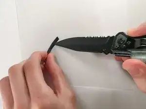
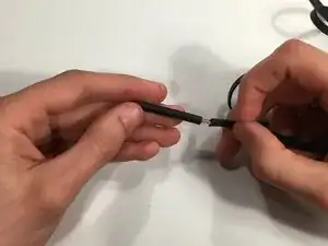
    • Cut the headphone cable near the old headphone jack. Leave some cable attached to the jack.

  2. HEZXwavvloKaALAU
    • Cut open the outer insulation of the cable connected to the old jack to expose the internal wires.

  3. HB4fmiZv2EgEZD5b
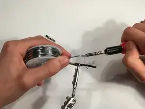
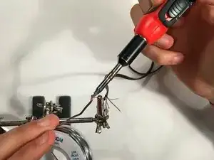
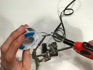
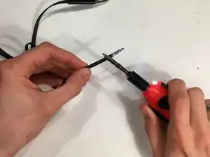
    • Apply a small amount of solder to the tips of each of the internal wires.

    • Make use of the Helping Hand tool to hold the wires while you apply the solder and iron.

    • Do not touch the soldering iron to the wire for a long period of time, you may melt through the wire.

  4. RtlnZFaEy5qeGRpj
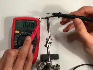
    • Turn on the multimeter and set it to measure resistance.

    • Select a wire and touch one of the multimeter leads to the soldered tip.

    • Touch the other multimeter lead to each of the segments on the headphone jack until the multimeter indicates that the wire is connected.

    • Make sure to record what wire is connected to what pole of the jack.

    • Repeat the process for each wire.

    Alternative repair suggestion — use a 4 pole headset cable, cut off the jack and solder the wires to the headphone’s cable, using solder and heatshrink tubing. This results in a stronger connection and it’s a lot easier to solder the wires to each other than to the tiny contacts on the plug.

    Wayne Seltzer -

  5. 6KblfX6TUWwRoxMP
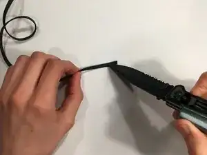
    • Cut away the insulation on the wire connected to the headphones.

  6. LVXJok1LLgpyTQxc
    • Select an appropriately sized piece of shrink tubing.

    • Slide the tubing over the wire.

  7. knSCELc4AcKjwNiO
    • Select a wire and apply a small amount of solder to the tip of the wire.

    • Repeat this for every wire.

  8. ikdMHBUidpXooqrp
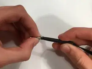
    • Position a wire to the corresponding connection point on the jack.

    • Carefully apply a small amount of solder to hold the wire in place.

    • Repeat this for each wire.

    • Make sure to reference the mapping of wires to connection points that you created in Step 4.

    • When soldering the wires, be patient and meticulous about getting the right position to make a good connection.

    • If the internal wires do not have their own insulation, use a small bit of shrink tubing on each wire. This will prevent them from shorting across another wire.

  9. c6RKuJ2oxdxiM1DR
    • Slide the shrink tubing back over the base of the jack, covering the soldered connections.

  10. S6RiwCOHOXi2Ffj3
    • Use the flat side of the soldering iron to apply heat to the shrink tubing until it tightens on the wire.

    • Alternatively, you could also use a heat gun or hair dryer.

Conclusion

You have now completed the replacement process. Plug it into an audio source and play some music to test your work.

Matthew Vaught

Member since: 30/03/16

1019 Reputation

12 comments

This is a plug replacement, not a jack replacement.

Wes Hartman -

This is a jack replacement.

Jonathan Harper -

can you please tell me which color wire and where to solder !

Sujith Kumar John G -

Wire colors are not standardized. They even differ among models of the same manufacturer. The only way is to test against the plug that is being replaced. Hopefully most wires still connect to the plug contacts, so a process of elimination can be used. Typical colors are red, blue, green and no color. Ground is usually no color, and sometimes there are 2 grounds (e.g. for ‘zipper’ style wires). The contacts for most phones are as follows (from tip to outside barrel): Right, Left, Ground, Mic. My Samsung S3 cord was very strange: red, green, no color and 2 black wires. One black was Ground, the other was MIC. Soldering requires a magnifier and a fine tipped iron.

Bert490 -

No pinout, seriously?

Old Liquid -

This is rated difficult, I'm trying to find a replacement plug that uses screws vs. soldering. There's a YouTube video on it, but screw plugs are almost impossible to find. I also don't have a multimeter. Another option is to have a repair shop do it - $20 was quoted (fixed or your money back.) …but that is not in the spirit of iFixit.

Jeff -

Im using the original jack after i cut off plastic insulation can u tell me which wires go to which solder points on the jack.

Kevin French -

This tutorial would be much more helpful if descriptions were added as to which portions of the plug (tip, ring 1, ring 2, ring 3) are used for earphone and which are used for microphone.

Pete WK8S -

This is a plug replacement, not a jack replacement. The “jack” is the “female” connector in your device. The “male” connector is a “plug”. Seriously get your basic terminology straight, even the part list calls for a “plug”. I have been looking for a jack replacement how to, but every result I get is for plug replacements calling the plugs jacks. Jack & plug are not interchangeable terms.

Nerfbomb -

This guide does not even explain which cable to solder where? There are four wires. Where does it go? How can this even be a guide if it is not even clear? Should this not be removed until it is properly curated?

D1Xenotime -

davvero molto utile e molto apprezzato il lavoro del traduttore Simone

Mattia Mengia -

Grazie Mattia, qualora volessi contribuire sentiti pure libero di apportare miglioramenti al testo

Simone -