
Introduction
Tools
Parts
-
-
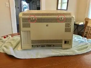
Follow the Apple Lisa Disassembly Guide to remove the Lisa's real panel.
-
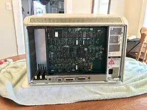
Remove the Lisa's Card Cage.
-
-
-
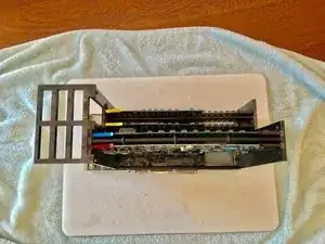
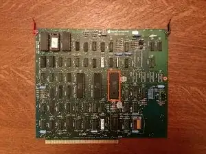
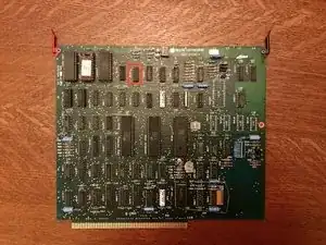
Remove the Lisa's I/O Board. The I/O Board's clips are marked in red.
-
Release both clips holding the I/O Board.
-
Pull the I/O Board up to remove it.
-
-
-
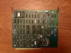
Next to the chip removed in step 3 is a crystal. These are not always installed with a plastic coating. The crystal shown in the image is insulated.
-
If your crystal is not insulated then tape a small piece of cardboard on top of it.
-
-
-
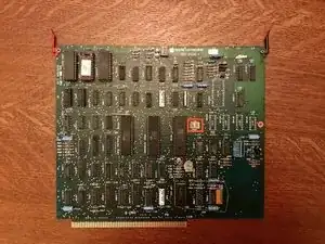
Ensure the pins on the MW+II PFG (Programable Frequency Generator) are perfectly straight. If they are not then slightly bend them into place.
-
Insert the PFG into the 8530 socket.
-
-
-
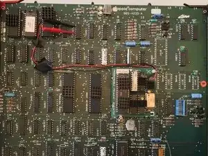
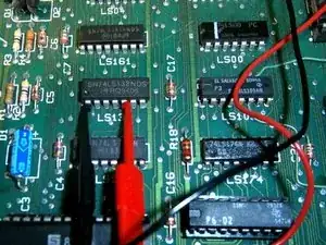
Locate the chip marked LS132 located at 6A.
-
Connect the Red and Black wires as shown in the second image on this step.
-
It is best to place a piece of electrical tape on the wires to help hold them in place.
-


- MW+II supports Macintosh System Software up to Macintosh System 7.5.5.
- Supports over 10MB of RAM (more than 4MB requires an XLerator.)
