Introduction
When it comes to building a computer it takes lots of time and determination to put everything together. By splitting up a big project into smaller pieces, the project becomes much less daunting. In this guide, I will detail how to hook up your front panel connectors from your computer chassis to your ATX Motherboard with ASUS Z490 Wi-Fi (ASIN: B086QSD3M4). In other words, I will teach you how to get your front panel inputs/outputs (Reset, Power On, LED Power light) to actually work.
When building a computer it is necessary to ensure that your motherboard is compatible with all other components including the computer chassis.
WARNING:
- Do not work on a motherboard on the carpet. Static electricity can fry the motherboard.
Tools
-
-
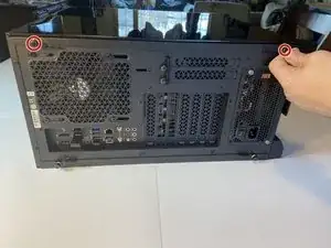
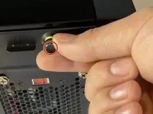
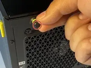
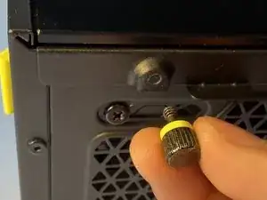
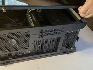
Once the screws are removed lift off the side panel to expose the motherboard and internal cables.
-
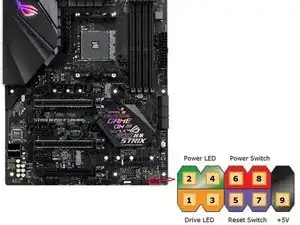
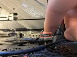
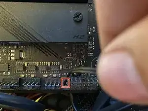
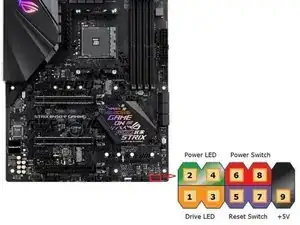
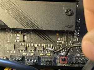
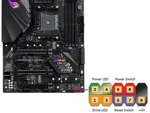
Locate where the front panel pins are.
-
-
-
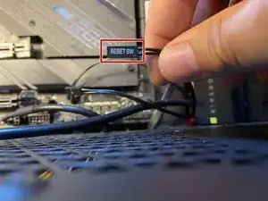
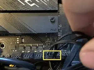
Plug the cable marked Reset SW into the motherboard. This will allow your reset button to actually work.
-
-
-
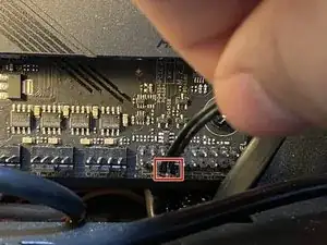
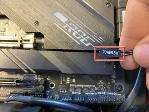
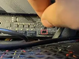
Plug the Power SW cable in above the Reset SW on the motherboard. This will allow you to turn on your computer with the power button on the front of your PC case.
-

To reassemble your device, follow the instructions, steps 1 and 2, in reverse order.

One comment
Petite précision :
Les broches sur lesquels il faut brancher les connecteurs des différents éléments du boitier sont indiquées dans la notice de la carte mère (button power, LEDs, etc.). L’emplacement et l’ordre de branchement des différents éléments du boitier est susceptible de varier selon le modèle de la carte mère.
Cela concerne aussi le buzzer si vous en avez un.
Brendan -