Introduction

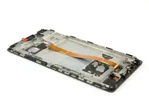
Use this guide to replace the defective display of your Huawei Mate 8.

  1. FPx6tr1SmACZCQLl
    FPx6tr1SmACZCQLl
    nV32foKH1fC3wQpp
    • Switch off your phone and remove the SIM card tray.

  2. MoPkyf5rJ1B6BDgK
    • Remove the Torx T2 screws from the bottom of the phone

  3. 2AIKFEMfSFQObbBo
    2AIKFEMfSFQObbBo
    GEZbwKnoJkZJmYmu
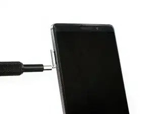
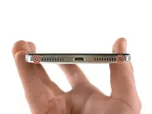
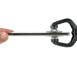
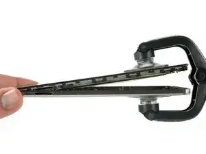
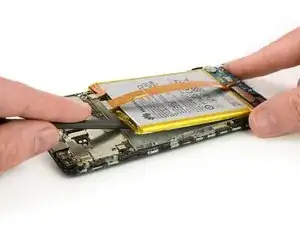
    • Use an iSclack or a suction handle in the bottom area of your phone to separate the display unit from the rear panel.

  4. nUkTUM4bAdfaScSX
    nUkTUM4bAdfaScSX
    j5FJXOAmFYNNasFl
    jHXPyaXbBMkd66un
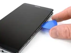
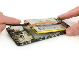
    • Use an opening pick to fully separate the clips, releasing the phone.

    • Do not fully remove the rear case. The fingerprint sensor cable is still connected to the back cover.

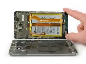
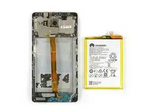
    • Open the phone like a book from the SIM tray side.

    • Use a spudger, to disconnect the fingerprint sensor cable.

  5. IVnKFFI2pYjFIGHs
    IVnKFFI2pYjFIGHs
    VjsdpGOfXllTC4Vr
    QaXBXHUyrByqcm6a
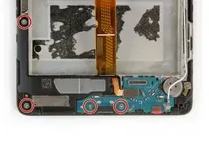
    • Remove the liquid indicator sticker.

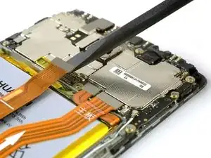
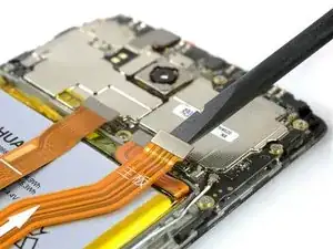
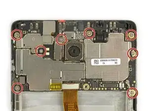
    • Remove the Phillips #00 screw that holds down the metal shield.

    • The metal shield is tightly held in place. If you try to remove it without holding it down on one side, it'll break easily.

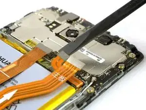
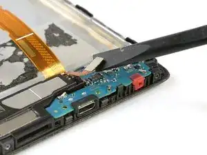
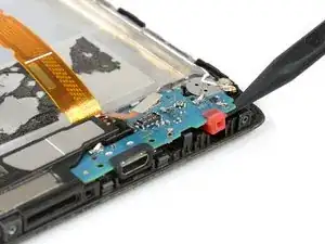
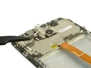
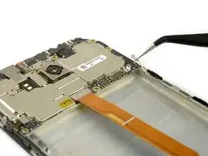
    • Use a spudger to remove the metal shield.

  6. K6orOuC2D6Rd4wDj
    K6orOuC2D6Rd4wDj
    1UuljImJHcSoWvB5
    2fGFVt4LOXi16CVI
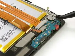
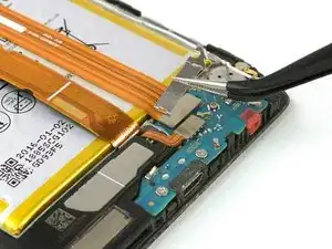
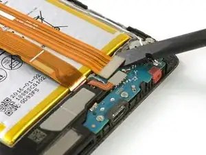
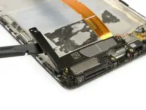
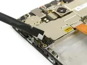
    • Use the flat end of a spudger to disconnect the display, daughterboard interconnect, and battery cables.

  7. k4FNj21sCTTJhxXb
    • Remove the Phillips #00 screw that holds down the interconnect cable bracket.

  8. YsSDABtcvNYWUN2G
    YsSDABtcvNYWUN2G
    VHrupamIvFWGy2EJ
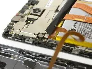
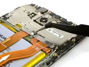
    • Lift the coaxial connector off of its socket to allow access to the daughterboard interconnect cable bracket.

    • Remove the bracket.

  9. esX2tEyJIi5UfMTS
    • Use a spudger to disconnect the interconnect cable.

    • Remove the interconnect cable.

  10. VGdDI3wIg13GpYnl
    • The battery is glued in place with two adhesive strips. One with a pull tab and one without.

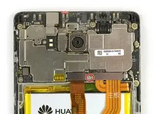
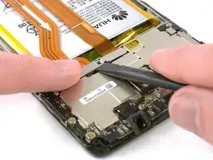
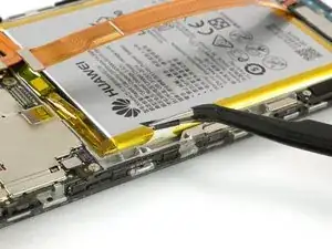
    • Get a good grip on the pull tab near the power button and peel out the adhesive strip by steadily pulling at the tab in a flat angle.

    • If the adhesive strip rips, grab and twist it around the tweezer tips a couple of times and then continue.

  11. KW2vFPuJwBR6Vjxj
    KW2vFPuJwBR6Vjxj
    vWPG2QbHY1SCGSvt
    FFPyAxKEAXiMnRpj
    • Do not bend or puncture the battery, damage to the cell can cause battery fires.

    • Heat an iOpener and place it on the phone for about a minute to loosen the remaining adhesive.

    • Carefully insert the flat end of a spudger to separate any remaining adhesive at the top of the battery.

  12. xiJFSRPgsCOSViyh
    xiJFSRPgsCOSViyh
    H5GFqYN4TNvvFXFL
    • Lift the top end of the battery to pull the battery off of the remaining adhesive strip.

    • When reassembling your phone, apply stretch release adhesive strips, double sided adhesive tape, or pre-cut adhesive to secure the new battery.

    • Never reinstall a battery that has been bent or damaged during removal.

  13. eY4LioDKIUZ3Rlt1
    • Remove the four Phillips #00 screws holding the daughterboard and loudspeaker to the phone.

  14. Cp2KXs5HpikcJ4Zk
    Cp2KXs5HpikcJ4Zk
    tVjCxjAEFmG2PnpP
    • Use the flat end of a spudger to disconnect the loudspeaker connector cable.

    • Use the tip of a spudger to lift the daughterboard from the phone.

  15. WDWJTTp1yE2DQsVk
    WDWJTTp1yE2DQsVk
    OJUoWcuMTGgVtqpX
    • Insert the flat end of a spudger under the loudspeaker at the gap on the left side.

    • Work the spudger under the loudspeaker to seperate it from the adhesive and remove the loudspeaker.

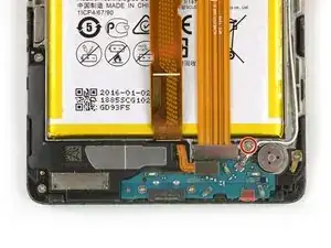
    • Use tweezers to take the vibration unit out of its housing.

  16. rDFKbN5626VJFwKq
    • Remove the eight Phillips #00 screws securing the motherboard to the phone.

  17. A2EUxnv4WgamFD3I
    A2EUxnv4WgamFD3I
    v6uaSQMiacnDFWOk
    • Remove the bracket from the rear camera flex cable.

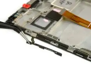
    • Use tweezers to disconnect the antenna cable.

  18. QksVcqYLk4Td4CmI
    QksVcqYLk4Td4CmI
    XwZhRWTFKMOdTX24
    ACsmcMWSpOYRHkhS
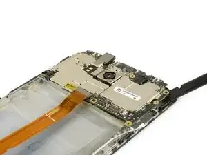
    • Use the flat end of a spudger to disconnect the volume and power flex cable on the bottom left side of the mainboard.

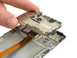
    • Work the flat end of a spudger under the top right side of the mainboard to pry it out.

    • Remove the mainboard.

  19. vaDMSHOSDuog2fKw
    vaDMSHOSDuog2fKw
    llJtKaWHOkJ6UDVa
    • Remove the antenna interconnect cable.

    • Remove the power and volume switch assembly.

  20. eYg3fOmaIlXTyOiS
    eYg3fOmaIlXTyOiS
    DhiCBKOSGHKyUQYL
    aP5mBOVDlIR3kEEM
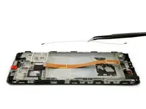
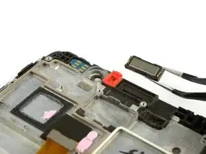
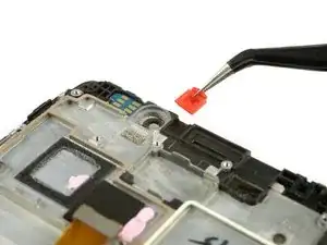
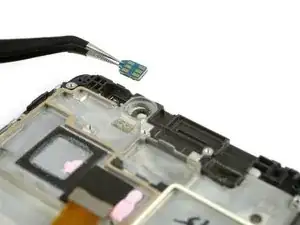
    • Use tweezers to remove the earpiece speaker.

    • Remove the red rubber gasket.

    • Remove the ambient light and proximity sensor.

Conclusion

To reassemble your device, follow these instructions in reverse order.

Dominik Schnabelrauch

Member since: 23/11/16

167327 Reputation

One comment

Tidy. Really tidy like.

Marc Vestabule -