Introduction

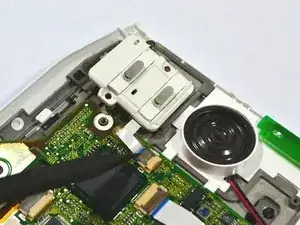
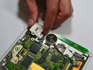
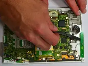
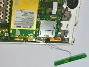
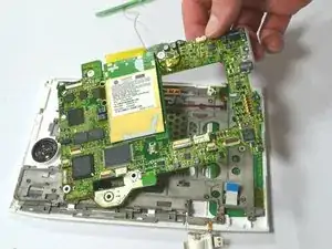
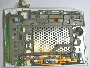
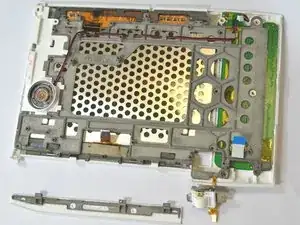
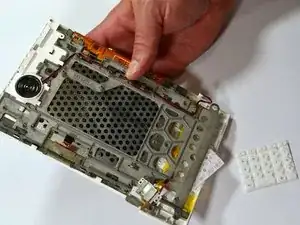
This guide covers the basic steps to replace the buttons of the keyboard on the First Generation Amazon Kindle.

  1. q1sA1XFbQnaOFrn5
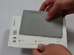
    • Slide the grey plastic cover laterally off the back of the device.

  2. RviTdAvCRHSK3YOF
    RviTdAvCRHSK3YOF
    khZOQcYguUUDL6YJ
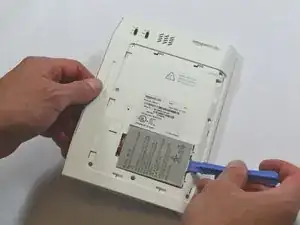
    • Use a plastic opening tool to lift the battery on the side closest to the edge of the device.

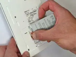
    • Unplug the battery from the device by pinching the white connector and pulling.

    • Do not yank the battery or try to disconnect the battery by pulling the wires.

    My present keyboard Kiindle model is 2nd gen-made in China…was warned at purchase by Amazon that it wld not be repairable… will your solution/battery repair work?

    Thanks,Dortrin

    Dorothy Trinen -

  3. DEkO6bMglDNcQ3ra
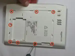
    • Unscrew eight (8) Phillips #00 screws (3 mm).

  4. kQh4t3DuW6lMKtvE
    kQh4t3DuW6lMKtvE
    ITyeUbdXZvLf356P
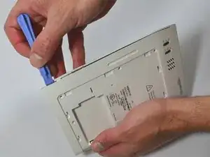
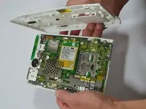
    • Start at one side of the device. Use a plastic opening tool to separate the casing of the device. Slowly work your way around the entire device.

    • Avoid prying between the buttons and the device. This could cause damage to the buttons.

  5. HBqMIRWUytUBWXWt
    HBqMIRWUytUBWXWt
    vXaikVCpkJSmWIrK
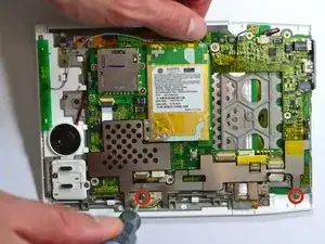
    • Unscrew the two (2) Phillips #00 screws (3 mm) which fasten the metal casing shield.

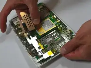
    • Slowly remove the metal casing shield by lifting it and carefully peeling up the tape.

  6. Pl1W6MvcuwxswP4f
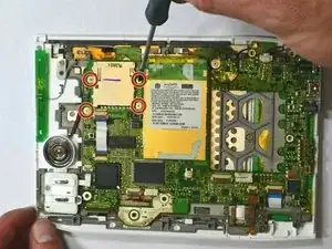
    • Remove the four (4) Phillips #00 screws (3 mm) which fasten the SD Card Reader.

  7. 1OYZ5UPEKu5MyxGP
    1OYZ5UPEKu5MyxGP
    aaYOKZnwBxYADANi
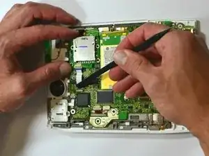
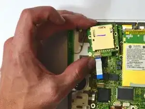
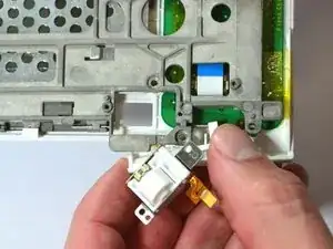
    • Lift the flap attaching the blue and white ribbon cable to the motherboard by lifting it vertically with a spudger.

    • The flap is connected via a hinge. Once you lift the flap, it will stay up and the cable will be lose. Remember to snap it back down during reassembly.

    • Carefully lift the SD Card Reader vertically from the motherboard.

  8. KKkaK35LQua1RnGX
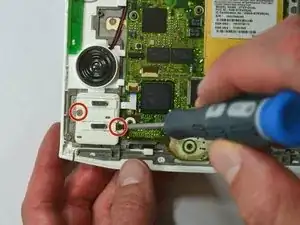
    • Remove the two (2) Phillips #00 screws (3 mm) connecting the ON/OFF Power and Wifi Switches.

  9. S5xXpnJHKDGpTfKy
    S5xXpnJHKDGpTfKy
    2JAqRa5pkHJy2WA5
    • Lift the flap attaching the blue and white ribbon cable to the motherboard by lifting it vertically with the pointed-end of the spudger.

    • The flap is connected via a hinge. Once you lift the flap, it will stay up and the cable will be lose. Remember to snap it back down during reassembly.

    • Carefully lift the ON/OFF Power and Wifi Switches vertically from the device motherboard.

  10. Y6IYOh1iSQZsThUV
    Y6IYOh1iSQZsThUV
    dsSkET2W1ZUXvqIr
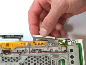
    • Use a spudger to remove the Wifi antenna from the device by carefully prying it up off the casing.

    • The Wifi antenna is attached to the device by a mild adhesive. Once the antenna is free from the adhesive, set the antenna off to the side.

    • Do not try to detach the antenna from the motherboard.

    Wire to antenna actually goes under the small metal piece at lower right of this image. The piece needs to be removed in order to get the antenna and motherboard away from the rest later.

    Reed Bowman -

  11. IqNCqj36nXUgcMTT
    IqNCqj36nXUgcMTT
    ONKNmKFSGY6FwF12
    KZpGpIb6o2XdTmmO
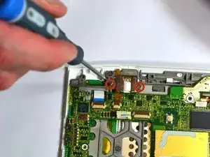
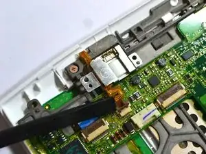
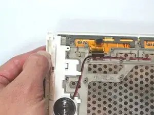
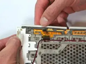
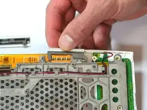
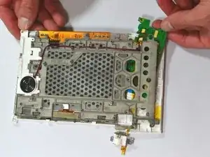
    • Unscrew the two (2) Phillips #00 screws (3 mm) attaching the scroll bar.

    • Use a spudger to lift the flap vertically in the second image to release the scroll bar from the motherboard.

    • The flap is connected via a hinge. Once you lift the flap, it will stay up and the cable will be lose. Remember to snap it back down during reassembly.

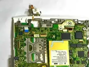
    • Do not pull the scroll bar off the device. Simply flip it around so it is out of the way for further disassembly, as seen in the third image.

  12. uQyXaKfuPj3JkpOQ
    uQyXaKfuPj3JkpOQ
    YPOGRNVDXQOWZEoE
    rRYMLZ5gbLDa4vXE
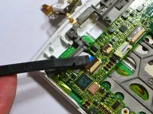
    • Lift the flap attaching the blue and white ribbon cable to the motherboard by lifting it vertically with the spudger.

    • Lift the flap with the pointed-end of the spudger to detach the ribbon cable indicated in the second image.

    • The flaps are connected via a hinge. Once you lift the flap, it will stay up and the cable will be lose. Remember to snap it back down during reassembly.

    • Use tweezers to pull the ribbon cable in the third image laterally to detach it.

  13. orrhYPApTMllimfu
    • Detach the cable by pulling laterally with tweezers or your fingertips. Do this by grasping the edges of the white connector and pulling laterally.

    • Grasp the end of the cable with tweezers or your fingertips and pull upwards to detach it from the motherboard.

    • Do not grasp either cable by the wires and attempt to pull them.

  14. jXKUSZ5tETTpIMkA
    jXKUSZ5tETTpIMkA
    Myd11XOMZ3y2W5JB
    jbMa4GQJdGUmR52n
    • Remove the two (2) Phillips #00 screws (3 mm) which attach the motherboard to the front casing.

    • Carefully lift the motherboard off.

    • The piece marked in the third image may be loose and fall out freely. If it does not fall off, use your fingers or a plastic opening tool to snap it off. Make sure to place it under the motherboard during reassembly, as found in the image.

  15. uFlRLnVkhEUPVs5Y
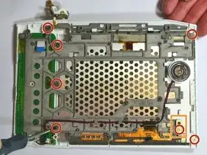
    • Remove the seven (7) Phillips #00 screws (3 mm) remaining on the frame.

    • The orange-marked metal piece is only held down by a screw and will become loose. Make sure to re-position it during assembly.

    The orange marked piece needed to be taken off earlier, because it holds the wire to the WiFi antenna down.

    Reed Bowman -

  16. saYNyIxcisStoFqh
    saYNyIxcisStoFqh
    MuYh6ZDqcqNNND1V
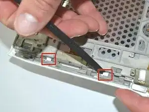
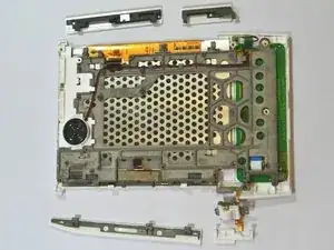
    • Press down firmly on the two white tabs, behind the large 'NEXT PAGE' button with the spudger. This will unsnap the front casing from the rest of the device.

    • The front case will begin to come loose. Do not try to pull it off.

    • Slide out the large 'NEXT PAGE' button laterally away from the keyboard.

  17. UWaYkT6cZOHiC2xc
    UWaYkT6cZOHiC2xc
    AApXoKCWmO1VXiAq
    • Slightly lift the top corner of the panel.

    • Slide the 'PREV PAGE' button out laterally towards the top corner.

  18. uiQBsPJQZuWMSsMO
    uiQBsPJQZuWMSsMO
    PoEGMyK2CJJliv2P
    • Slide out the small 'NEXT PAGE' button laterally towards the keyboard.

  19. N32xZuYOIIGtLGWj
    N32xZuYOIIGtLGWj
    gUqDTfUyqUv3mYwZ
    • Slide out the small 'BACK' button laterally towards the keyboard.

  20. CKN4GJkHCEZUbejo
    CKN4GJkHCEZUbejo
    WloIS3oTlWLvQT26
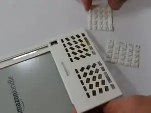
    • The keyboard and the blue and white ribbon cable will slide out horizontally from behind the frame.

    • The rubber key pads will slide out from behind the frame.

Conclusion

To reassemble your device, follow these instructions in reverse order.
Samantha Manning

Member since: 04/06/13

766 Reputation

0 comments