
Introduction
Use this guide to replace your MacBook Air's upper case. The upper case includes the keyboard and trackpad.
-
-
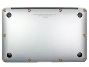
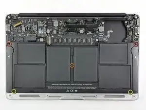
Remove the following ten screws:
-
Two 8 mm 5-point Pentalobe screws
-
Eight 2.5 mm 5-point Pentalobe screws
-
-
-
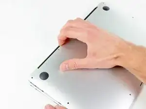
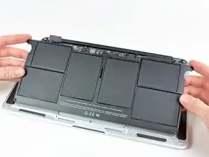
Wedge your fingers between the display and the lower case and pull upward to pop the lower case off the Air.
-
Remove the lower case and set it aside.
-
-
-
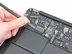
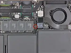
Use the flat end of a spudger to pry both short sides of the battery connector upward to disconnect it from its socket on the logic board.
-
Bend the battery cable slightly away from the logic board so the connector will not accidentally contact its socket.
-
-
-
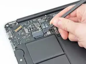
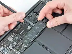
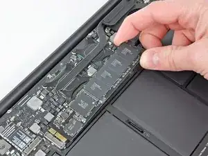
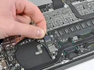
Use a spudger to help lift the free end of the SSD just enough to grab it with your other hand.
-
Pull the drive straight out of its socket and remove it from the logic board.
-
-
-
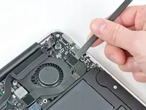
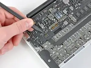
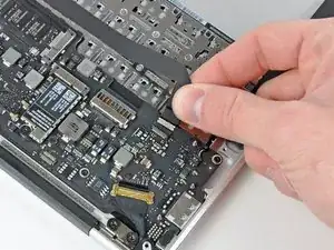
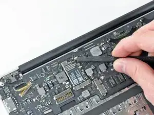
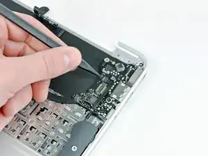
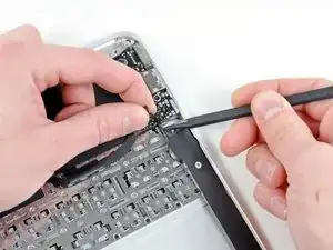
Use the flat end of a spudger to pry the I/O board cable connector upward out of its socket on the I/O board.
-
-
-
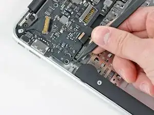
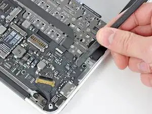
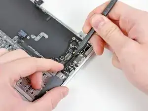
While gently pulling the I/O board cable upward near its connection to the logic board, use the tip of a spudger to pry upward on alternating sides of the connector to help "walk" it out of its socket.
-
Remove the I/O board cable.
-
-
-
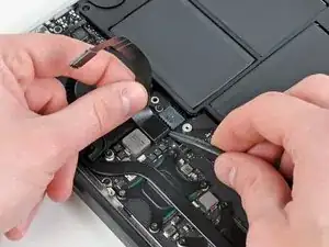
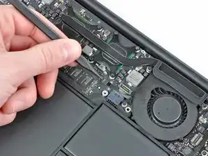
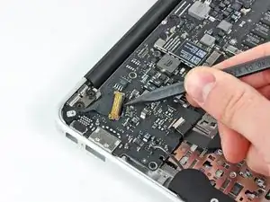
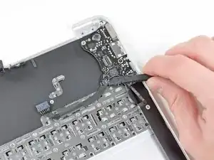
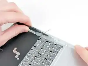
Use the tip of a spudger to carefully flip up the retaining flap on the fan cable ZIF socket.
-
-
-
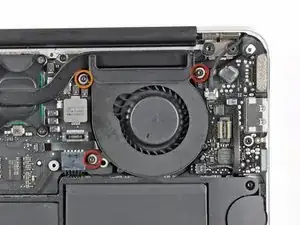
Remove the following three screws securing the fan to the upper case:
-
Two 5.2 mm T5 Torx screws
-
One 3.6 mm T5 Torx screw
-
-
-
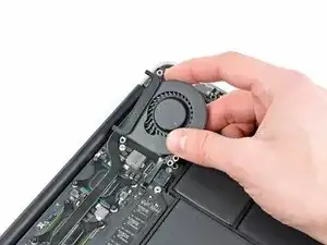
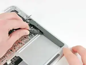
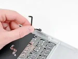
Lift the fan out of the upper case and carefully pull the fan ribbon cable out of its socket as you remove it from the Air.
-
-
-
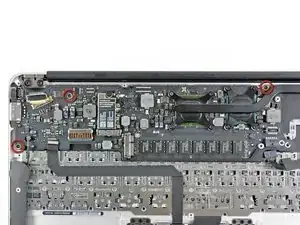
Remove the following five screws securing the battery to the upper case:
-
Two 5.2 mm T5 Torx screws
-
One 6 mm T5 Torx screw
-
Two 2.6 mm T5 Torx screws
-
-
-
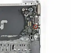
Disconnect the I/O board by pulling the power cable away from its socket on the logic board.
-
-
-
Use the tip of a spudger or your fingernail to flip up the retaining flap on the trackpad ribbon cable ZIF socket.
-
Pull the trackpad ribbon cable straight out of its socket toward the front edge of the Air.
-
-
-
Use the tip of a spudger to de-route the right speaker cable from the slot cut into the logic board.
-
-
-
Use the flat end of a spudger to pry the right speaker cable connector up and out of its socket on the logic board.
-
-
-
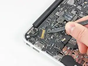
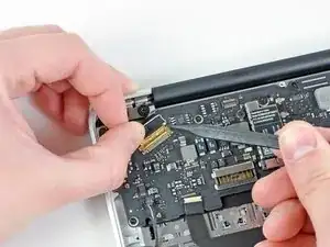
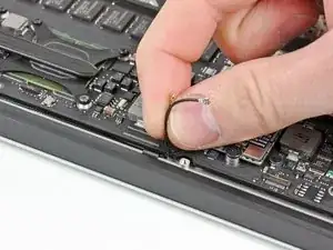
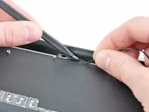
Gently push the tip of a spudger under the black plastic flap stuck to the display data cable lock to make the lock pop upward and away from the socket.
-
While holding the lock away from the socket, use the tip of a spudger and your fingers to gently remove the display data cable from its socket.
-
-
-
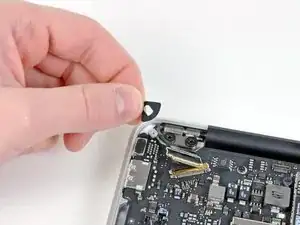
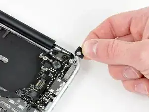
Remove the small rubber gasket from the corner of the upper case near the display data cable.
-
-
-
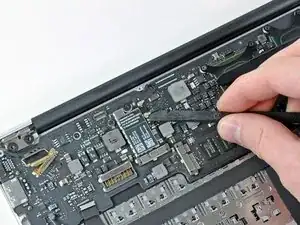
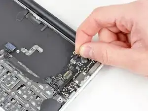
Use the flat end of a spudger to pry both antenna cable connectors up and off their sockets on the AirPort/Bluetooth card.
-
-
-
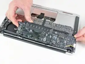
Gently lift the logic board assembly out of the upper case, minding the fragile heat sink and any cables that may get caught.
-
-
-
Pull the camera cable parallel to the face of the I/O board toward the rear edge of the Air to disconnect it from its socket.
-
-
-
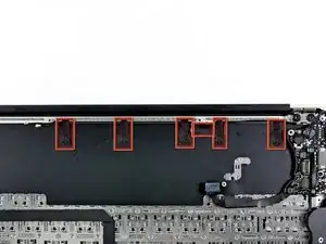
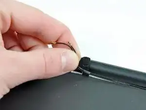
Peel up the six cable loops securing the antenna cables to the upper case.
-
Gently pull the cable loops slightly out of the channel cut into the upper case one at a time.
-
Use your spudger to open up the plastic loops as you de-route the antenna cables through them.
-
Repeat this for all five retaining loops.
-
-
-
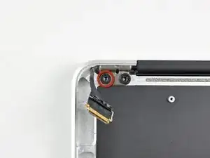
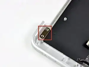
Remove the outer 4.9 mm T8 Torx screw securing each display hinge to the upper case (two screws total).
-
-
-
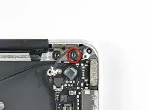
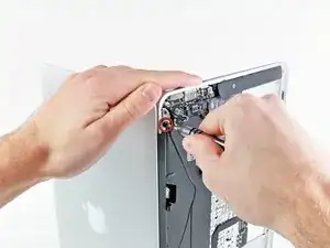
Open the display until it is perpendicular to the upper case and place it on a table as shown.
-
While holding the Air steady, remove the remaining 4.9 mm T8 Torx screw from the lower display bracket.
-
-
-
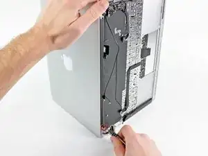
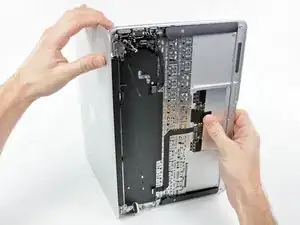
Push the upper case slightly toward the display assembly, then rotate it away from the front of the display assembly.
-
Once the two display hinges have cleared the upper case, remove the display and set it aside.
-
-
-
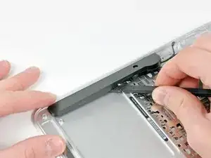
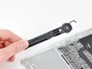
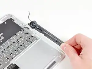
Use the flat end of a spudger to pry the right speaker off the adhesive securing it to the upper case.
-
Remove the right speaker from the upper case.
-
-
-
Use the tip of a spudger to carefully flip up the retaining flap on the microphone cable ZIF socket.
-
Pull the microphone ribbon cable straight out of its socket.
-
-
-
Use the flat end of a spudger to pry the left speaker cable connector up and out of its socket on the I/O board.
-
De-route the left speaker cable from the notch cut into the I/O board.
-
-
-
Carefully lift the I/O board from its edge nearest the logic board and remove it from the upper case.
-
-
-
Use the flat end of a spudger to pry the left speaker off the adhesive securing it to the upper case.
-
Remove the left speaker from the upper case.
-
-
-
Use the tip of a spudger to pry the microphone away from the side of the upper case.
-
Remove the microphone from the upper case.
-
Upper case remains.
-

To reassemble your device, follow these instructions in reverse order.

I recommend that one of the tools you obtain is a jeweler's loupe that mounts on your glasses. It makes things easier.
blairweaver -
This is not correct. You need the pentalobe tool at this point.
Duane Hellums -